akpedeye kelvin - hamk
TRANSCRIPT
8/13/2019 Akpedeye Kelvin - hamk
http://slidepdf.com/reader/full/akpedeye-kelvin-hamk 1/62
Advancement on Drilling Technology in Petroleum Industry
ADVANCEMENT ON DRILLING TECHNOLOGY IN
PETROLEUM INDUSTRY
Bachelor‟s thesis
Mechanical Engineering and Production Technology
Riihimäki 14.12.2010
_____________________
Akpedeye, Kelvin Uruemu
8/13/2019 Akpedeye Kelvin - hamk
http://slidepdf.com/reader/full/akpedeye-kelvin-hamk 2/62
Advancement on Drilling Technology in Petroleum Industry
BACHELOR‟S THESIS
Mechanical Engineering and Production Technology
Riihimäki
Title Advancement on Drilling Technology in Petroleum Industry
Author Akpedeye, Kelvin Uruemu
Supervised by Tapio Väisänen,
Approved on 18.12.2010
Approved by
8/13/2019 Akpedeye Kelvin - hamk
http://slidepdf.com/reader/full/akpedeye-kelvin-hamk 3/62
Advancement on Drilling Technology in Petroleum Industry
ABSTRACT
Riihimäki
Mechanical Engineering and Production Technology
Production Systems
Author Akpedeye, Kelvin Uruemu Year 2010
Subject of Bachelor’s thesis Advancement on Drilling Technology in Petro-
leum Industry
ABSTRACT
Since the birth of petroleum business, in the mid-19th century, cable tool
and rotary drilling have been the only two techniques applied in the drill-
ing phase till date. Although the rotary drilling technique has proved very
successful, applying laser technology in this drilling; which is a newer
technology that is already at hand, has the potential of displacing both
techniques from operation.
Cable tool drilling is the first of these techniques. Hole boring is achieved
by repeatedly lifting and dropping a heavy string of drilling tool into the bore hole with the bit crushing the rocks into small fragments. Compara-
tively, much success was not achieved with this because it is time consum-
ing, has a very low penetration rate, blowout preventers were not easily
adapted and it is almost limited to drilling consolidated formations. How-
ever, at the turn of the 20 th century, the rotary drilling technique was intro-
duced and it immediately displaced the cable tool from operation. The ma-
jor difference between both is that with the cable tool, drilling has to be
stopped in other for cuttings to be removed from the hole, whereas with
the rotary drilling, a mud circulates through the system and carries away
cuttings from the whole whilst drilling continues.
Rotary technique operation is more like a common hand held drill, rotating
drill bit with an applied force to drill down the earth crust. The prime
mover, hoisting equipment, rotating equipment, circulating equipment and
blowout preventers complement each other to give the rotary technique its
status in today‟s drilling. These five distinct components make a compli-
8/13/2019 Akpedeye Kelvin - hamk
http://slidepdf.com/reader/full/akpedeye-kelvin-hamk 4/62
Advancement on Drilling Technology in Petroleum Industry
cated looking rotary facility very understandable. Unlike the cable tool; it
can drill through most rock formations, has a high penetration rate and can
drill deeper wells, blowout preventers are easily adapted and can drill di-
rectionally as well.
However, applying laser technology in petroleum drilling, a fairly recent
development has the potential of mitigating the limitations of the state-of-
the-art technique. Experiments carried out so far on different types of la-
sers have shown very positive tendencies. One was conducted on
MIRACL (Mid Infrared Advanced Chemical Laser) to determine its feasi-
bility for drilling and perforating petroleum wells and another was on
COIL (Chemical Oxygen-Iodine Laser) to determine the least specific en-
ergy (SE) needed to destroy varying rock types. Each of these has cleared
the doubts of whether or not lasers technology can be applied in well op-
erations.
Keywords Drilling, blowout, laser, petroleum.
Pages 54 pp. + appendices 2 pp.
8/13/2019 Akpedeye Kelvin - hamk
http://slidepdf.com/reader/full/akpedeye-kelvin-hamk 5/62
Advancement on Drilling Technology in Petroleum Industry
CONTENTS
1 INTRODUCTION ....................................................................................................... 1 2 AIMS AND DELIVERABLES ................................................................................... 3 3 ANALYSIS OF TASKS .............................................................................................. 4 4 PROJECT TIMELINE ................................................................................................ 5 5 BACKGROUND ......................................................................................................... 6 6 LITERATURE REVIEW ............................................................................................ 7
6.1 Ancient Chinese Bamboo Drilling ...................................................................... 7 6.2 Cable Tool Drilling Technique ........................................................................... 8 6.3 Rotary Drilling Technique .................................................................................. 9 6.4 Laser Technology in Petroleum Drilling ............................................................. 9
7 HISTORICAL BACKGROUND .............................................................................. 11 7.1 Prehistoric – 18000............................................................................................ 11 7.2 1800 – 1860 ....................................................................................................... 12 7.3 1860 – 1901 ....................................................................................................... 12 7.4 1901 – 1930 ....................................................................................................... 13 7.5 1930 – 1945 ....................................................................................................... 14 7.6 1945 – 1965 ....................................................................................................... 15
8 RESULT: DRILLING TECHNIQUES ..................................................................... 17 8.1 Cable Tool Drilling Technique ......................................................................... 17
8.1.1 Cable Tool Drilling String Components ................................................ 19 8.1.2 Cable Tool Bailers ................................................................................. 20 8.1.3 Cable Tool Casing Driving Equipment ................................................. 20 8.1.4 Advantages of Cable Tool Drilling ....................................................... 22 8.1.5 Disadvantages of Cable Tool Drilling ................................................... 23
8.2 Rotary Drilling Technique ................................................................................ 23 8.2.1 The Prime Movers ................................................................................. 25 8.2.2 Hoisting Equipment ............................................................................... 25 8.2.3 The Rotating Equipment ........................................................................ 26 8.2.3.1 Rotary Drill Bits .................................................................................... 26 8.2.4 The Cirtulating System .......................................................................... 27 8.2.5 Blowout Preventers (BOP) .................................................................... 30 8.2.6 Directional Drilling ............................................................................... 34 8.2.7 Drilling Fluids ....................................................................................... 36 8.2.8 Advantages of Rotary Drilling .............................................................. 46 8.2.9 Disadvantages of Rotary Drilling .......................................................... 46
8.3 Laser Drilling Technique .................................................................................. 47 9
DISCUSSION ............................................................................................................ 49
10 CONCLUSION ......................................................................................................... 51

8/13/2019 Akpedeye Kelvin - hamk
http://slidepdf.com/reader/full/akpedeye-kelvin-hamk 6/62
Advancement on Drilling Technology in Petroleum Industry
11 REFERENCES .......................................................................................................... 52
Appendix 1 Definition of Terms
8/13/2019 Akpedeye Kelvin - hamk
http://slidepdf.com/reader/full/akpedeye-kelvin-hamk 7/62
Advancement on Drilling Technology in Petroleum Industry
1
1 INTRODUCTION
Even at the beginning of the 21st century, the petroleum industry is yet to overcome
some major problems it faces in the operations. A major focus is on the drilling
practices. This makes it difficult for the industry to get the results they require with-
in the shortest possible time. Hence a lot of time is put into drilling, sometimes
weeks or even months, just a single well.
„„Edwin Drake drilled the first well, for the purpose of petroleum production, in
1859 in Venango County, near Titusville in Pennsylvania‟‟. (Department of Envi-
ronmental Protection, 2009). Although, some claims of prior art do exist, (e.g.
Germany in 1857 and Canada in 1858), Drake‟s well at Titusville is still registered
as the first to be copied. He and his crew drilled in the manner of salt well drillers
but used a steam engine to power the drill and a piping to prevent borehole col-
lapse, allowing for the drill to penetrate further into the ground. This gave a pro-
gress of three feet (1m) per day. However, they hit their first production depth of
69.5feet (21m) drilling from spring to August 27. Since then, a variety of drilling
mechanisms has been developed and modified to sink a borehole into the ground.
Each has its own advantages and disadvantages, in terms of depth to which it candrill, the type of sample returned, the cost involved and penetration rate achieved.
A radical change occurred at the turn of the 20th century. The introduction of the ro-
tary drilling that displaced the then very popular cable tool drilling as a standard
method for reaching oil and gas ''traps'' down through the formation. Limitations
such as; downtime due to dull bits, lack of precise vertical or horizontal wells, for-
mation fluid leakage during drilling and waste created by drilling mud still persist
with this state-of-the-art basic mechanical method. In addition, drilling for petrole-
um and gas get increasingly difficult by the day. Nowadays, we are required to drill
as far as 25000feet (7620m), most times, in deep stormy waters in order to get a
satisfying volume. Hence the need for a more efficient drilling technique still re-
mains a constant goal.
Although, laser drilling experiments dates back to the 1960s, it is only recently that
experts started looking towards applying it to petroleum and gas drilling. “In 1997,
8/13/2019 Akpedeye Kelvin - hamk
http://slidepdf.com/reader/full/akpedeye-kelvin-hamk 8/62
Advancement on Drilling Technology in Petroleum Industry
2
the Gas Technology Institute (GTI) initiated a two-year study exploring the feasi-
bility of adopting high-powered military lasers for a revolutionary application in the
oil and gas exploration and production.” (Gahan., Richard, Gas Technology Insti-
tute; Samih, Colorado School of Mines; Humberto Figueroa, PDVSA-Intevep,
S.A.; Claude, Xu, Argonne National Laboratory. 2001) The experiment shows that
laser drilling stands a viable option to improve drilling technologies, especially in
offshore operations. Downtimes created by dull bits are drastically reduced as bits
are replaced with laser heads that have no contact with the rock and also waste cre-
ated by drilling mud is eliminated. It seals the wall of the well bore as it bores by
creating a ceramic sheath. This eliminates the cost of employing steel wall casing,
as influx/out-fluxes of fluids in and out of the well is eliminated and hence, prob-
lem of formation collapse is drastically reduced. In addition, it penetrates over 100
times faster than conventional rotary methods.
8/13/2019 Akpedeye Kelvin - hamk
http://slidepdf.com/reader/full/akpedeye-kelvin-hamk 9/62
Advancement on Drilling Technology in Petroleum Industry
3
2 AIMS AND DELIVERABLES
Although, this report was submitted to Glyndwr University, Wrexham, Wales –
United Kingdom, in April 2010, as my bachelor‟s dissertation. It is as well submi t-
ted to Hamk University of Applied Sciences, Finland in December 2010 and serves
as my bachelor‟s thesis. This was so because I went on exchange to Glyndwr Uni-
versity and completed my dissertation there as part of my graduation modules.
This project is aimed at highlighting a new drilling technique that can be applied by
petroleum and gas industries to optimize drilling practices and hence, production.
This research work briefly outlines the first petroleum and gas drilling techniques
and follows the trend to today's methods in a chronological order. Emphasis will be
on the problems associated with each method and how they were overcome by sub-
sequent ones.
However, a major part of this research will be on analysis of a viable drilling tech-
nique that stands a chance of supplanting the present state-of-the-art method that
was invented over 100years ago. Laser technology in petroleum well drilling offers
a very new approach and might just be another long awaited revolutionary change
in petroleum and gas drilling technologies.
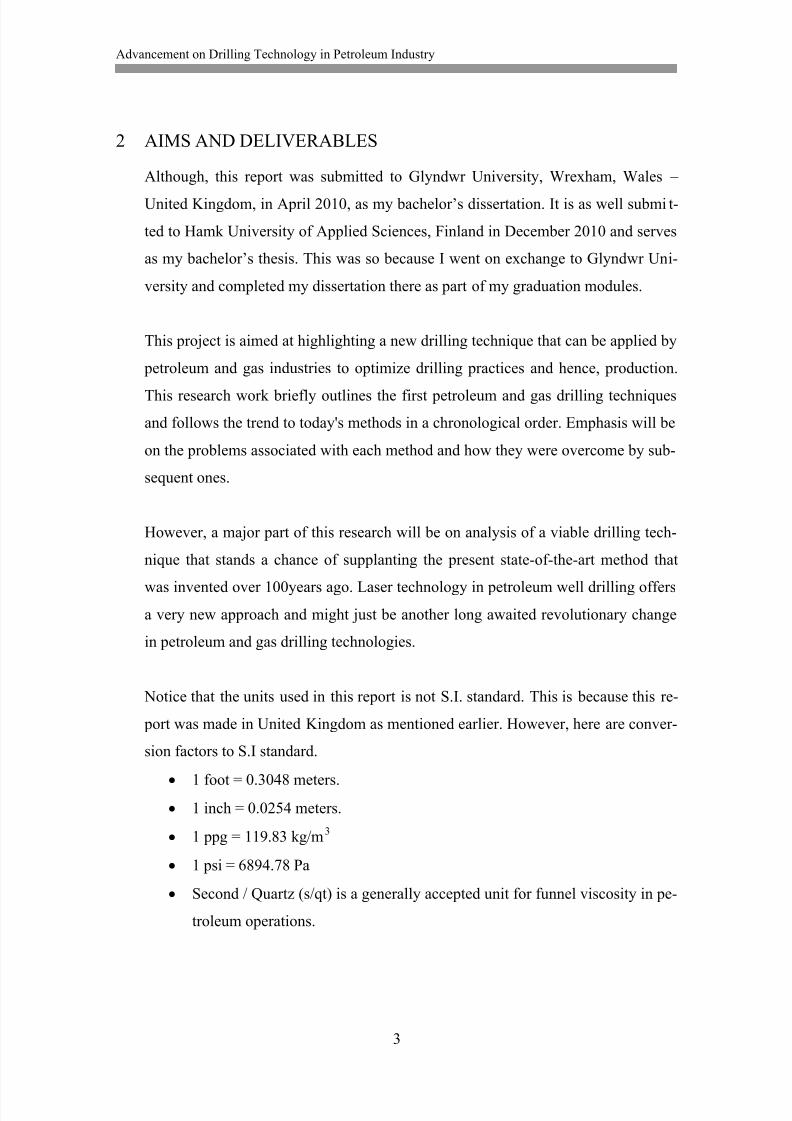
Notice that the units used in this report is not S.I. standard. This is because this re-
port was made in United Kingdom as mentioned earlier. However, here are conver-
sion factors to S.I standard.
1 foot = 0.3048 meters.
1 inch = 0.0254 meters.
1 ppg = 119.83 kg/m3
1 psi = 6894.78 Pa
Second / Quartz (s/qt) is a generally accepted unit for funnel viscosity in pe-
troleum operations.
8/13/2019 Akpedeye Kelvin - hamk
http://slidepdf.com/reader/full/akpedeye-kelvin-hamk 10/62
Advancement on Drilling Technology in Petroleum Industry
4
3 ANALYSIS OF TASKS
Research materials and information on the overview of this subject were gathered
from textbooks, journals as well as materials from the internet. Laboratories and
organizations carrying out tests on the feasibility of applying laser technology to
drilling for petroleum and gas were also contacted. This was to get first hand results
and observations. However, companies directly involved in the drilling phase of pe-
troleum and gas exploration and exploitation were also contacted. This is to appre-
ciate the realistic problems they face using varying drilling techniques as well as to
have their opinion on the research. The research materials were collated, studied
and comprehensively discussed. Afterwards, realistic conclusions were drawn.
8/13/2019 Akpedeye Kelvin - hamk
http://slidepdf.com/reader/full/akpedeye-kelvin-hamk 11/62
Advancement on Drilling Technology in Petroleum Industry
5
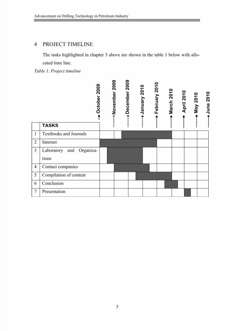
4 PROJECT TIMELINE
The tasks highlighted in chapter 3 above are shown in the table 1 below with allo-
cated time line.
Table 1. Project timeline
TASKS
1 Textbooks and Journals
2 Internet
3 Laboratory and Organiza-
tions
4 Contact companies
5 Compilation of content
6 Conclusion
7 Presentation
O c t o b e r 2 0 0 9
M a y 2 0 1 0
J u n e 2 0 1 0
D e c e m b e r 2 0 0 9
J a n u a r y 2 0 1 0
F e b r u a r y 2 0 1 0
A p r i l 2 0 1 0
N o v e m b e r 2 0 0 9
M a r c h 2 0 1 0
8/13/2019 Akpedeye Kelvin - hamk
http://slidepdf.com/reader/full/akpedeye-kelvin-hamk 12/62
Advancement on Drilling Technology in Petroleum Industry
6
5 BACKGROUND
Drilling is a cutting process in which a hole is produced or enlarged in a solid mate-
rial. In petroleum production, the solid material is the earth's formation. Hence, cre-
ating or enlarging a hole with specifications through the formation to the traps in
the reservoir rocks deep down in the subsurface to suck out petroleum, which has
been collected over years, safely is what petroleum drilling phase is all about. Over
the years, many processes have been invented and modified. From the bamboo rigs
used by the Chinese, to cable tool used in the 19 th century, down to the state-of-the-
art rotary drilling and now to the expected laser drilling, the race is still on for the
most effective process to optimize cost, time and efficiency.
Laser is an acronym for Light Amplification by Stimulated Emission of Radiation.
It is a device that emits light (electromagnetic radiations) through a process called
stimulated emission. Basically, lasers convert different forms of energy such as
chemical, electrical, heat, etc., into energy of light (intense photon) (Mustafiz et al.,
2004). Lasers can be operated either in Continuous-Wave (CW), Normal Pulsed
(NP), or Repetitively Pulsed (RP) mode respectively. (Graves & O'Brien, 1998)
They added that the output power P is the main energetic parameter for a laser op-
erating in the CW mode, the output energy Q for the NP mode and the average
power P and pulsed energy Q for the RP mode.
However, three basic phenomena; reflection, scattering and absorption determines
the process of transferring this radiant energy into the rock. This transfer eventually
causes destruction of the rock and under controlled conditions, drilling fine hole.Absorption is the process by which heat is collected by the rock and thus results in
tearing the rock apart. On the other hand, both scattering and reflection represents
the energy losses or the heat not absorbed by the rock. In conventional drilling sys-
tems, factors such as weight-on-bit (WOB), mud circulation rate, rotary speed, hy-
draulic horsepower bit design and hole size all affect the rate at which a borehole is
created. With Laser drilling, this rate only depends on the delivered power and the
size of the hole, thus, eliminating the complexities of the current drilling system.
(Graves & O'Brien, 1998).
8/13/2019 Akpedeye Kelvin - hamk
http://slidepdf.com/reader/full/akpedeye-kelvin-hamk 13/62
Advancement on Drilling Technology in Petroleum Industry
7
6 LITERATURE REVIEW
6.1 Ancient Chinese Bamboo Drilling
The earliest evidence of wells in China, in Zhejiang Province comes from
the era when humans were first turning to agriculture in this region, some
7,000 years ago. (Oliver, n.d.) He added that about 5,000 years ago, the
Chinese boiled sea water to produce salt and as the need for salt increased
with increase in population, they needed to go underground and started
digging for brine, to meet up with the demand of salt. He pointed out that
the first recorded salt well in China was dug in Sichuan Province around
2,250 years ago.
Around 2,000 years ago, there was a noticeable change from the use of
hand and shovels dug wells to percussively drilled ones. The drilling tech-
nique used is still seen today in China in the rural areas. Basically, the drill
bit is made of iron and the pipe, bamboo. He added that the rig is con-
structed from bamboo; one or more men stand on a wooden plank lever,like a child's seesaw, and this lifts up the drill stem about 1m. The pipe is
allowed to drop down with one man holding it and ensuring that it goes
straight in the direction needed. As it crashes into the rock, it pulverizes it
and slowly, the drilling progresses. This might take months in most cases
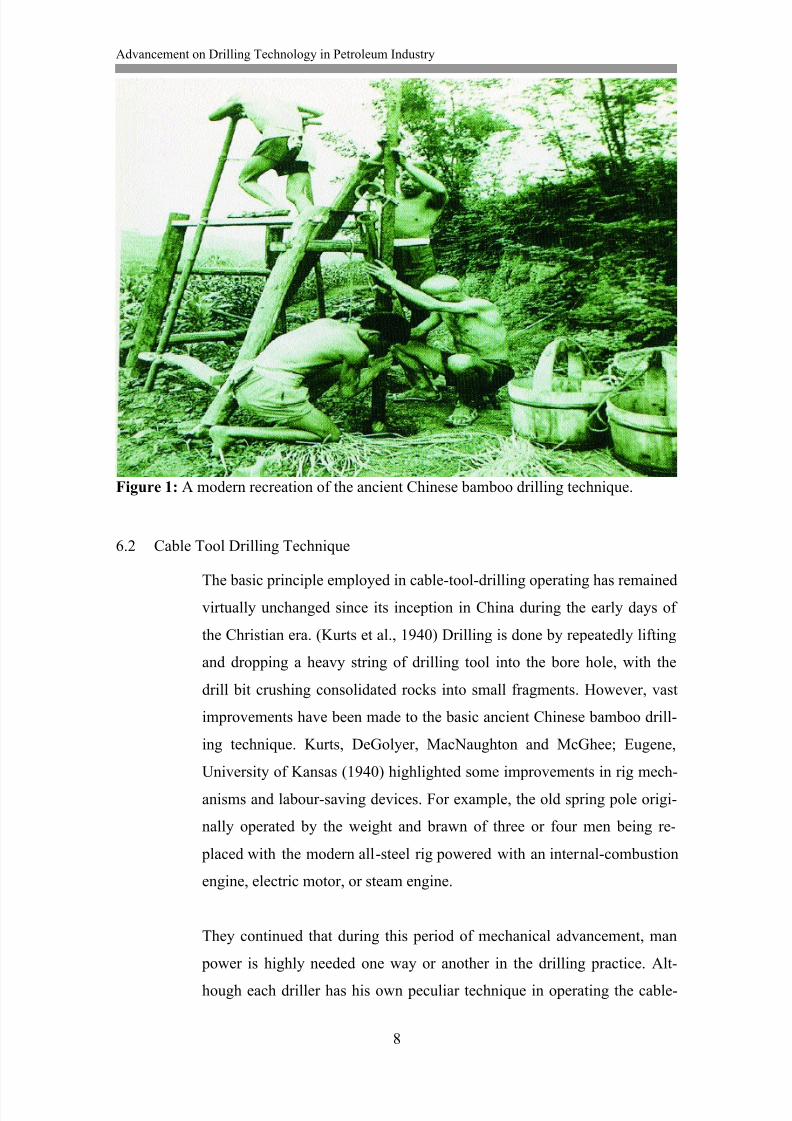
(Oliver, n.d.). This is shown in the figure 6.1 below.
Another noticeable change, as documented by Oliver, n.d., happened
around 1050 AD. Solid bamboo pipe was replaced by thin, light, flexible
bamboo. This allowed for deeper wells to be drilled as well as it lowered
the weight that needed to be lifted from the surface. By the 1700s, wells as
deep as 300 – 400m deep were drilled and in 1835, the Shanghai well was
the first in the world to exceed 1000m in depth. About that time in the US,
the deepest wells were around 500m in depth. This drilling method on its
own is impressive, especially when compared to what the rest of the world
had to offer about that time.
8/13/2019 Akpedeye Kelvin - hamk
http://slidepdf.com/reader/full/akpedeye-kelvin-hamk 14/62
Advancement on Drilling Technology in Petroleum Industry
8
Figure 1: A modern recreation of the ancient Chinese bamboo drilling technique.
6.2 Cable Tool Drilling Technique
The basic principle employed in cable-tool-drilling operating has remained
virtually unchanged since its inception in China during the early days of
the Christian era. (Kurts et al., 1940) Drilling is done by repeatedly lifting
and dropping a heavy string of drilling tool into the bore hole, with the
drill bit crushing consolidated rocks into small fragments. However, vast
improvements have been made to the basic ancient Chinese bamboo drill-
ing technique. Kurts, DeGolyer, MacNaughton and McGhee; Eugene,
University of Kansas (1940) highlighted some improvements in rig mech-
anisms and labour-saving devices. For example, the old spring pole origi-
nally operated by the weight and brawn of three or four men being re-
placed with the modern all-steel rig powered with an internal-combustion
engine, electric motor, or steam engine.
They continued that during this period of mechanical advancement, man
power is highly needed one way or another in the drilling practice. Alt-
hough each driller has his own peculiar technique in operating the cable-
8/13/2019 Akpedeye Kelvin - hamk
http://slidepdf.com/reader/full/akpedeye-kelvin-hamk 15/62
Advancement on Drilling Technology in Petroleum Industry
9
tool, the good driller is distinguished from the poor one by the footage he
makes in a given period of time, they added.
6.3 Rotary Drilling Technique
Dr. Claude, (2009) pointed out clearly that it was at the turn of the 20 th
century (approximately 100 years ago) that saw to the birth of the rotary
drilling as a standard method of reaching oil and gas formations. It was
about this time that this basic mechanical method served as an option and
phased out the cable tool drilling method, he added. Since its birth, major
improvements have occurred but in the last couple of decades, the method
of drilling has not changed at all. (Irfan, Mohit, Nakul, Vickey, Nikhil,
Anand, SPE, Maharashtra Institute of Technology, Pune. 2009)
The American Oil & Gas Historical Society (2006) summarized the basic
difference between the rotary and the cable-tool drilling technique. ''In-
stead of the repetitive lift and drop of heavy cable-tool bits, the rotary
drilling introduced the hollow drill stem which enables rock debris to be
washed out of the bore hole with re-circulated mud while the rotating drill
bit cuts deeper.'' They added that the rotary drilling fluid (drilling mud),
that is used to circulate out the chipped rock, washes the bore hole clean
and makes the drilling exercise more efficient. The drilling mud equally
helps the well against bursting forth unexpectedly. This is so because the
mud controls the pressure difference between itself in the bore hole and
that fluid in the formation.
6.4 Laser Technology in Petroleum Drilling
The work accomplished so far on laser drilling has resulted in some posi-
tive indications (Mustafiz, Bjorndalen, and Islam. 2004). They added that
although experiments on laser drilling were conducted between 1960s and
1970s, it is only very recently that the application of laser technology is di-
rected to drilling petroleum wells. However, a suggestion in 1990 had it
that application of laser technology in petroleum drilling is not feasible,
but this was because the experiments conducted then, in this regard, were
8/13/2019 Akpedeye Kelvin - hamk
http://slidepdf.com/reader/full/akpedeye-kelvin-hamk 16/62
Advancement on Drilling Technology in Petroleum Industry
10
made with low powered lasers (less than 1kiloWatt). However, current ex-
periments have proved it otherwise. (Mustafiz et al., 2004)
Graves & O'Brien (1998) highlighted some very significant importance la-
ser drilling would have over conventional rotary drilling method. These
include:
drilling over 100 times faster
cutting off downtime due to dull bits
drilling more precise vertical and horizontal wells
eliminating formation fluid leakage during drilling
eliminating wastes created by drilling mud and rock cuttings
cost effectiveness by decreasing current drilling times.
They added however, that a combination of laser and rotary drilling is not
out of thought, as this would result in an increase in bit life. Other possi-
bilities with the advancement of laser technology include; development of
down hole drilling machine, laser-assisted drill bits, laser-perforation
tools, and sidetrack and directional laser drilling devices. Hence, the
thought of applying laser technology being a viable option for enhancing
the petroleum drilling phase.
8/13/2019 Akpedeye Kelvin - hamk
http://slidepdf.com/reader/full/akpedeye-kelvin-hamk 17/62
Advancement on Drilling Technology in Petroleum Industry
11
7 HISTORICAL BACKGROUND
7.1 Prehistoric – 18000
The earliest holes dug into the earth were done in search of food, water,
protection and for building habitats or escape route from enemies. Many
of these holes, especially by those who spent their lives underground were
done developing special parts of their bodies as digging tools such as ad-
aptations of claws and feeds, jaws, heads, etc.
Early man, having no usable claws, found it necessary to use hand tools –
such as sticks, bones and naturally shaped stones – as digging tools. After
many many years of evolutionary processes, he eventually learned to
shape sticks and poles to make them more efficient digging tools. He was
then able to dig reasonable vertical wells with these tools and throwing the
cuttings to the surface.
About 600 B. C. In China, Confucius wrote of wells drilled for brine. Alt-hough, the exact depths of these wells were not given, but they were ap-
parently deeper than hand dug wells. The Chunking region near the border
of Tibet where these wells were drilled is still undergoing drilling for brine
from near 600 B.C. To present times. These wells varied in depths of
around 4,000ft and an estimation of wells as deep as 1,500 ft (approxi-
mately 460m) dug as early as 1200 A.D.
During the years preceding 1800, there has never been much need to go
beneath the surface of the earth except in the arid country. In England and
around Europe, the industrial revolution made a modest beginning for go-
ing more underground. The water required then by these industries how-
ever, were gotten from shallow hand dug wells or just on the surface of
earth. (Dr. Brantly 1971.)
8/13/2019 Akpedeye Kelvin - hamk
http://slidepdf.com/reader/full/akpedeye-kelvin-hamk 18/62
Advancement on Drilling Technology in Petroleum Industry
12
7.2 1800 – 1860
During the late 1700 and early 1800, most families in America moved
with the early explorer‟s westward beyond the blue-ridge mountain and
settled in areas like Western Virginia, Western Pennsylvania, Western
New York, Ohio and Kentucky. Before long, a modest rural economy was
created that required everyday commodity like sodium chloride salt. This
initiated the collection of brine by the early hunters. They dug shallow pits
on the seepage areas, accumulated brine, concentrated it by boiling and the
salt was precipitated off.
David and Joseph Ruffner – brothers – carried on their fathers brine busi-
ness with hand dug pits. At some point, the demand exceeded their supply.
''They conceived the idea of drilling a hole into the earth to intercept the
source of the brine, thus increasing the supply and obtaining a more highly
concentrated liquid'' (Dr Brantly, 1971, 6). Between 1806 – 08, they com-
pleted the first well drilled in America for the purpose of brine. It is about
58ft deep. Following the success of the Ruffner well, many others were
drilled succeeding 50years or more for brine from which salt could be pre-
cipitated. However, it was discovered that the brine being sought was as-
sociated with petroleum traces.
Whereas, the Ruffner brothers developed the earliest American well-
boring tool for the purpose of brine, William Drake developed on their
technique by introducing a steam engine to power the process, and drilled
for the purpose of producing oil and gas for commercial use in 1859. (Dr.
Brantly, 1971.)
7.3 1860 – 1901
The Drake well drilled in 1859 to 69.5ft was the first in America drilled
for petroleum production in commercial quantity. Following the next 40
years, several others were drilled in many other countries including; Can-
ada, around Europe, the middle east, the east Indies, Argentina, New Zea-
land, and others. ''During this period in America, cable tool drilling
8/13/2019 Akpedeye Kelvin - hamk
http://slidepdf.com/reader/full/akpedeye-kelvin-hamk 19/62
Advancement on Drilling Technology in Petroleum Industry
13
equipment developed from the rather crude rigs of the 1850's to common
cable tool drilling rig of the 1870's'' (Dr. Brantly, 1971, 9). This became
the standard cable tool drilling that was used across countries until about
1925.
Although wooden drilling rods were famous with percussion tool drilling
prior to 1860, American operators changed to manila drilling cable after
1860 and to steel cable in the early 1900's. Whereas in Canada, wooden
drill rods were retained in the early 1900's and was moved to the Galacian
(Poland) oil fields. Rods became the standard on European rigs; wood in
the lighter rigs, and steel or wrought iron on heavy/big hole tools.
''In the early 1880's, the Baker brothers of South Dakota developed a fluid
circulating rotary rig for drilling shallow water wells in the unconsolidated
formations of the Great Plains'' (Dr. Brantly, 1971, 10). The Texas oil field
was discovered during the 1890's and the cable tools could not be used sat-
isfactorily in that, the formation is soft and unconsolidated. The new rota-
ry rig that were drilling water wells of comparable formations was then
employed in this Corsicana field about 1895, and by 1900 several hundredwells were drilled along the Gulf coast. (Dr. Brantly, 1971.)
7.4 1901 – 1930
Around late 1890's and early 1900's, great attention was giving to develop-
ing tools and drilling practices for drilling wells in the relatively soft and
unconsolidated beds of the Golf coastal formations. This Corsicana rig,
which is a modification of the Baker brother‟s fluid circulating rotary rig,
was an important one in this regard. The Lucas Spindle top well, which
blew in January 10, 1901, was brought under control, completed and pro-
duced in commercial quantity by a Corsicana rig and a carefully selected
Corsicana crew.
The new rotary rigs were moved to many soft formation areas where cabletool had failed, because of its inability for the tool to get to required depths
8/13/2019 Akpedeye Kelvin - hamk
http://slidepdf.com/reader/full/akpedeye-kelvin-hamk 20/62
Advancement on Drilling Technology in Petroleum Industry
14
in soft unconsolidated formations. During the first five years preceding the
completion of the Lucas well, some 1000 rotary wells, either for water, pe-
troleum, Sulphur or salt, were drilled in the Gulf coastal plains of Texas.
However, in the first six years, nearly 4000 wells were drilled with rotary
rigs mainly for petroleum in the coastal regions.
With the rotary rigs unfortunately, difficult problems with drilling through
hard formations and hard rocks were encountered. In 1909, Howard R
Hughes designed a roller cutter: comprising replaceable rolling cutters and
this was successful. The Hughes' and several other roller cutters were de-
veloped and improved over the years until about 1930 when the design be-
came similar to that of today. In addition, the combination rotary rig was
equally developed, still as a result of the problems encountered by the ro-
tary rigs in drilling hard formations or through hard rocks. They were
erected in areas where such conditions were known or expected. The com-
bination rig has a cable tool built inside. This invention persisted until
about 1930 as well. (Dr. Brantly, 1971.)
7.5 1930 – 1945
Firstly, by 1930, a new rotary drilling rig was designed. This equipment
had greater depth capacity per ton of weight, drilled faster holes and was
reasonably trouble free compared with the one replaced. As further years
role by, many improvements were made – like the introduction of drilling
feed control based on weight on the bit in 1934.
During the World War II, when a bulk of engineers became engaged with
designing war equipment, drilling efficiency declined drastically. This was
obviously as a result of shortages of experienced men and partly shortage
in new replacement units for old rigs. Happily, by the end of the war in
1945, it gained back its pre-war status, as design engineers returned to
their normal work of designing and preparing drawings for petroleum well
drilling equipment.
8/13/2019 Akpedeye Kelvin - hamk
http://slidepdf.com/reader/full/akpedeye-kelvin-hamk 21/62
Advancement on Drilling Technology in Petroleum Industry
15
In addition to what happened at the end of the war, programs on educating
drilling crew in care and maintenance of drilling equipment, drilling fluid
controls, drilling practices and safety precautions were renewed. Older
men, who had gone into the war activities were recruited back and were
involved in the intensive training programs, as well as new personnel. (Dr.
Brantly, 1971.)
7.6 1945 – 1965
1945 was a very important year for petroleum drilling business because as
the war ended, the foundries, forgers and lathes of the oil field equipment
manufacturers were cleared off military hardware as quick as possible and
was replaced with machinery, tools and equipment required for drilling
wells for petroleum production. Many of the new designs and shop draw-
ings were ready including equipment to be built into power rigs. This sea-
son marked the end of designing rigs with steam engines.
In addition, improved internal combustion engines, hydraulic drives,
clutches, gear trains and chains, etc that were predominant in equipment
used during the war had usefulness in oil field equipment. They were im-
proved and incorporated into the drilling equipment. ''Pumps were equally
redesigned to meet the requirements of new drilling practices, requiring
higher pressure drilling fluids than previously used'' (Dr. Brantly, 1971,
22). Downhole tools were not exempted in these general improvements.
Basically, the predominating roller cutter rock bit was improved and steels
were a better option for the roller cutters and body of the tools. In addition,
diamond set bits was developed as cutting tools. ''They are now one of the
principal and most important cutting tools in hard formations'' (Dr. Brant-
ly, 1971, 23).
Considerable improvement also took place in the instrumentation applica-
tions between these years and specifically in 1969, there were already in-
struments that indicated the instant value of any given drilling factor gavecumulative values and recorded these values. Drilling parameters includ-

8/13/2019 Akpedeye Kelvin - hamk
http://slidepdf.com/reader/full/akpedeye-kelvin-hamk 22/62
Advancement on Drilling Technology in Petroleum Industry
16
ing; the nature of the drilling characteristics of the formation, the function-
ing of the down hole tool and others of interest and assistance to the drill-
ers became easy to get, following these improvements. (Dr. Brantly,
1971.)
8/13/2019 Akpedeye Kelvin - hamk
http://slidepdf.com/reader/full/akpedeye-kelvin-hamk 23/62
Advancement on Drilling Technology in Petroleum Industry
17
8 RESULT: DRILLING TECHNIQUES
A successful well drilling, whether on land or offshore, must be able to provide;
a means of fracturing and penetrating through rock formations to reach
petroleum and gas,
a means of excavating the rock cuttings off the bore hole,
a means of preventing the walls of the bore hole from collapsing or cav-
ing in, especially when drilling through unconsolidated formations,
The diameter of the well must be large enough to permit lowering tools
down the hole and permit application of newer drilling techniques.
Although the rotary drilling technique is used more frequently today, the cable-
tool is still used in some cases nevertheless.
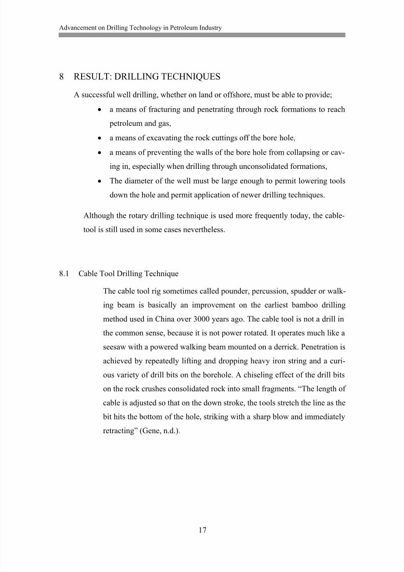
8.1 Cable Tool Drilling Technique
The cable tool rig sometimes called pounder, percussion, spudder or walk-
ing beam is basically an improvement on the earliest bamboo drilling
method used in China over 3000 years ago. The cable tool is not a drill in
the common sense, because it is not power rotated. It operates much like a
seesaw with a powered walking beam mounted on a derrick. Penetration is
achieved by repeatedly lifting and dropping heavy iron string and a curi-
ous variety of drill bits on the borehole. A chiseling effect of the drill bits
on the rock crushes consolidated rock into small fragments. “The length of
cable is adjusted so that on the down stroke, the tools stretch the line as the
bit hits the bottom of the hole, striking with a sharp blow and immediately
retracting” (Gene, n.d.).
8/13/2019 Akpedeye Kelvin - hamk
http://slidepdf.com/reader/full/akpedeye-kelvin-hamk 24/62
Advancement on Drilling Technology in Petroleum Industry
18
Figure 2: Cable Tool Drilling Rig
The drilling process has to be stopped at intervals to get rock cutting off
the bore hole and water is added either by the driller or flows in from the
formation to do this. The water mixes with the crushed rock particles and
8/13/2019 Akpedeye Kelvin - hamk
http://slidepdf.com/reader/full/akpedeye-kelvin-hamk 25/62
Advancement on Drilling Technology in Petroleum Industry
19
turns it into slurry that settles at the bottom of the bore hole. At a point
where the slurry accumulates to a quantity that begins to reduce the pene-
tration to an unaccepted level, drilling is stopped and the slurry is removed
by a bailer. The bit is reinstalled into the hole and drilling continues after
each stage of removing slurry.
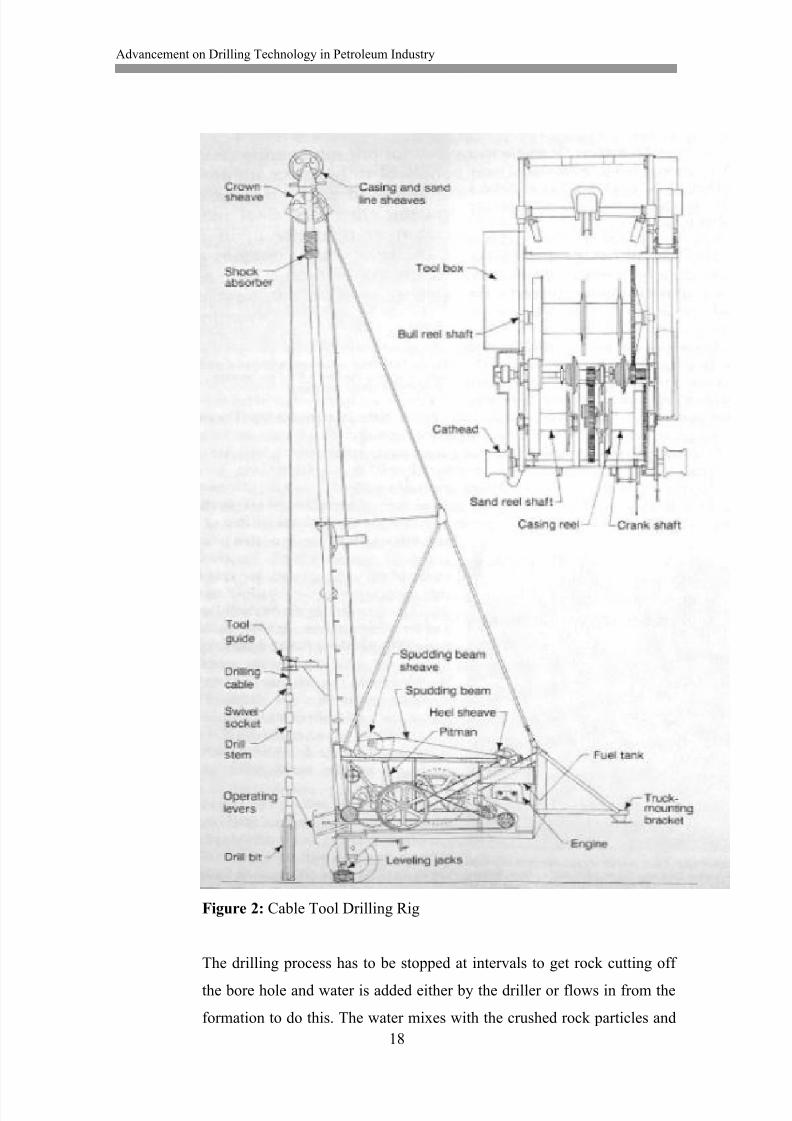
8.1.1 Cable Tool Drilling String Components
A cable tool string has four basic components:
Drilling Cable – lifts tools, turns tools, controls tool motion.
Swivel Socket – connects cable to tools, allows cable to unwind.
Drill Stem – provides weight, steadies and guides bits.
Drill Bit – penetrates formation, crushes and reams mixes cut-
tings.
Figure 3: Cable Tool Drilling String Components
Drilling jars may be added to the drill string. They don‟t play any role in
the drilling process per se, but depending on the formation, they may be
8/13/2019 Akpedeye Kelvin - hamk
http://slidepdf.com/reader/full/akpedeye-kelvin-hamk 26/62
Advancement on Drilling Technology in Petroleum Industry
20
needed to provide a hammering action that frees tools that become
jammed.
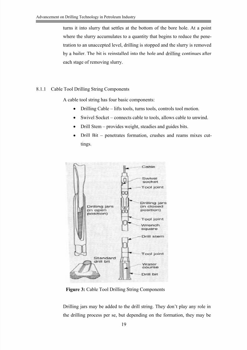
8.1.2 Cable Tool Bailers
Bailers are metallic pipes with a one-way flapper valve on the lower end.
They are attached to an eye in the end of a separate line called the bailing
or sand line respectively. The drill string is removed from the hole and the
sand line, carrying the bailer, is lowered in to remove the chips cut by the
drill bit for drilling to proceed. Selection of the most suitable bailer de-
pends on how well the slurry is mixed. Below are some common types.
Figure 4: Cable Tool Bailers
8.1.3 Cable Tool Casing Driving Equipment
As pressure increase with depth of drilling, there is need for casing to pro-
tect caving in of the formation. The casing is driven down by a force pro-
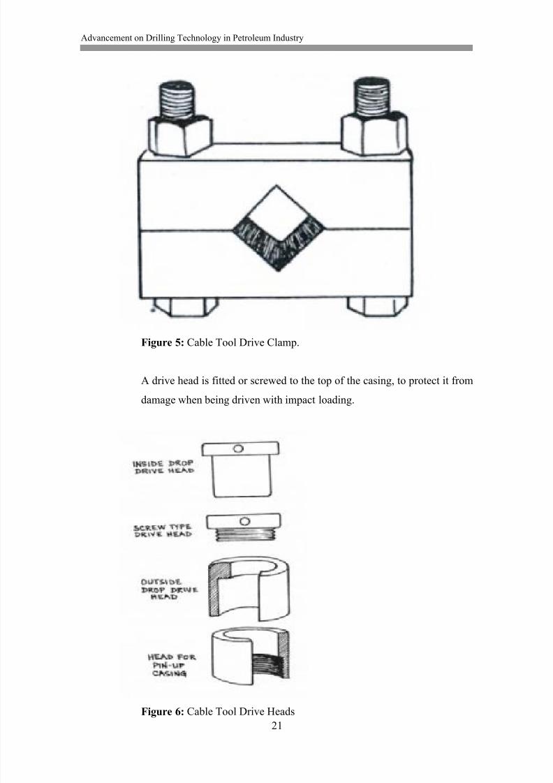
vided by the drive clamp attached to the drill string. A wrench square isforged in the drill stem to allow for the attachment of the drive clamp.
8/13/2019 Akpedeye Kelvin - hamk
http://slidepdf.com/reader/full/akpedeye-kelvin-hamk 27/62
Advancement on Drilling Technology in Petroleum Industry
21
Figure 5: Cable Tool Drive Clamp.
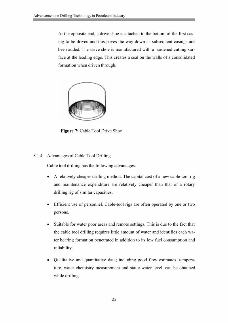
A drive head is fitted or screwed to the top of the casing, to protect it from
damage when being driven with impact loading.
Figure 6: Cable Tool Drive Heads
8/13/2019 Akpedeye Kelvin - hamk
http://slidepdf.com/reader/full/akpedeye-kelvin-hamk 28/62
Advancement on Drilling Technology in Petroleum Industry
22
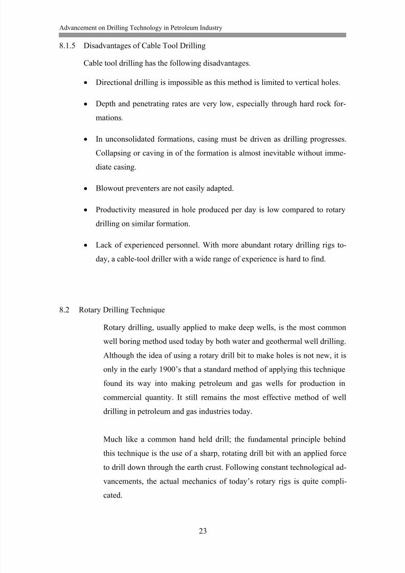
At the opposite end, a drive shoe is attached to the bottom of the first cas-
ing to be driven and this paves the way down as subsequent casings are
been added. The drive shoe is manufactured with a hardened cutting sur-
face at the leading edge. This creates a seal on the walls of a consolidated
formation when driven through.
Figure 7: Cable Tool Drive Shoe
8.1.4 Advantages of Cable Tool Drilling
Cable tool drilling has the following advantages.
A relatively cheaper drilling method. The capital cost of a new cable-tool rig
and maintenance expenditure are relatively cheaper than that of a rotary
drilling rig of similar capacities.
Efficient use of personnel. Cable-tool rigs are often operated by one or two
persons.
Suitable for water poor areas and remote settings. This is due to the fact thatthe cable tool drilling requires little amount of water and identifies each wa-
ter bearing formation penetrated in addition to its low fuel consumption and
reliability.
Qualitative and quantitative data; including good flow estimates, tempera-
ture, water chemistry measurement and static water level, can be obtained
while drilling.
8/13/2019 Akpedeye Kelvin - hamk
http://slidepdf.com/reader/full/akpedeye-kelvin-hamk 29/62
Advancement on Drilling Technology in Petroleum Industry
23
8.1.5 Disadvantages of Cable Tool Drilling
Cable tool drilling has the following disadvantages.
Directional drilling is impossible as this method is limited to vertical holes.
Depth and penetrating rates are very low, especially through hard rock for-
mations.
In unconsolidated formations, casing must be driven as drilling progresses.
Collapsing or caving in of the formation is almost inevitable without imme-
diate casing.
Blowout preventers are not easily adapted.
Productivity measured in hole produced per day is low compared to rotary
drilling on similar formation.
Lack of experienced personnel. With more abundant rotary drilling rigs to-
day, a cable-tool driller with a wide range of experience is hard to find.
8.2 Rotary Drilling Technique
Rotary drilling, usually applied to make deep wells, is the most common
well boring method used today by both water and geothermal well drilling.
Although the idea of using a rotary drill bit to make holes is not new, it is
only in the early 1900‟s that a standard method of applying this technique
found its way into making petroleum and gas wells for production in
commercial quantity. It still remains the most effective method of well
drilling in petroleum and gas industries today.
Much like a common hand held drill; the fundamental principle behind
this technique is the use of a sharp, rotating drill bit with an applied force
to drill down through the earth crust. Following constant technological ad-
vancements, the actual mechanics of today‟s rotary rigs is quite compli-
cated.
8/13/2019 Akpedeye Kelvin - hamk
http://slidepdf.com/reader/full/akpedeye-kelvin-hamk 30/62
Advancement on Drilling Technology in Petroleum Industry
24
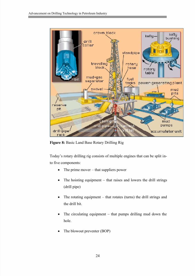
Figure 8: Basic Land Base Rotary Drilling Rig
Today‟s rotary drilling rig consists of multiple engines that can be split in-
to five components:
The prime mover – that suppliers power
The hoisting equipment – that raises and lowers the drill strings
(drill pipe)
The rotating equipment – that rotates (turns) the drill strings and
the drill bit.
The circulating equipment – that pumps drilling mud down the
hole.
The blowout preventer (BOP)
8/13/2019 Akpedeye Kelvin - hamk
http://slidepdf.com/reader/full/akpedeye-kelvin-hamk 31/62
Advancement on Drilling Technology in Petroleum Industry
25
8.2.1 The Prime Movers
The prime movers are the power house of the entire rig, in that they pro-
vide the energy needed to power the entire equipment in the rig. Steam
engines used to be popular with the early rigs but today‟s rigs make more
use of gas or diesel engines. In addition to the hoisting, rotating and circu-
lating equipment it powers, are compressors and provision of incident
lighting that are not directly related with drilling.
8.2.2 Hoisting Equipment
The hoisting equipment consists of tools used to raise and lower whatever
other equipment that in and out of the well. It is composed of the draw
works (pulleys), drilling lines, crown block, travelling block and the hook.
The derrick is the most visible part of the hoisting equipment and it serves
as support for the cables (drilling lines), draw works as well as to hold the
monkey board in place.
Because well are drilled with long strings of pipes (drill pipes) that extend
from the surface down to the drill bit, there is need to raise them all out
and lower them back in if there is problem that would require the need to
change the drill bit. The combine weight of the drill pipes, drill bits and
drill collars are in excess of thousands of pounds in deep wells. The hoist-
ing equipment is used to raise all of this to the surface should the need
arise.
The height of the derrick can give a clue as to how deep a well is. Normal-
ly, drill pipes come in single units of 1.83 – 3.66 feet each. This means
that even if the well is 182.88 feet deep, the drill string will be taken out in
bits of 1.83 – 3.66 feet sections. However, if the derrick is tall enough,
multiple sets of drill pipes may be removed at once and saving time.
8/13/2019 Akpedeye Kelvin - hamk
http://slidepdf.com/reader/full/akpedeye-kelvin-hamk 32/62
Advancement on Drilling Technology in Petroleum Industry
26
8.2.3 The Rotating Equipment
The rotating equipment consists of components that receives power from
the prime mover and transfers it down to the drill bit for it to crush or drill
ahead. The prime mover transfers power to the rotary table. The rotary ta-
ble is connected to the drill pipe and as it turns the drill pipe, the drill bit
turns respectively as it is connected to the drill pipe. A component called
the swivel, which is attached to the hoisting equipment, carries the entire
weight of the drill string, but allows it to turn freely.
Drill collars come between the drill bit and the drill pipe. They are heavi-
er, thicker and stronger than drill pipes and are used to add weight to the
drill string to provide enough downward pressure needed for the drill bit to
drill through hard rock formations. The down hole condition experienced
while drilling determines the number and nature of drill collars needed on
any particular rotary rig. This can be altered appropriately.
Rotary Drill Bits
On the rotary drilling rig assembly, the drill bit is located at the bottom
end of the drill string and is responsible for the actual cutting process as
well as dislodging rock, sediments and anything else encountered during
drilling. A conventional drill bit has three movable cones containing teeth
made of materials, like tungsten carbide, steel, diamond etc, tougher and
harder than the rock they are designed to cut through.
Drill bits used in rotary drilling are classified as follows:
Roller bits (or roller-cone bits).
o Steel tooth bits
o Insert bits (or tungsten carbide insert bits)
Fixed cutter drill bits.
o Polycrystalline Diamond Compacts (PDC) bits
o Thermally Stable Polycrystalline (TSP) bits
o Natural diamond bits
8/13/2019 Akpedeye Kelvin - hamk
http://slidepdf.com/reader/full/akpedeye-kelvin-hamk 33/62
Advancement on Drilling Technology in Petroleum Industry
27
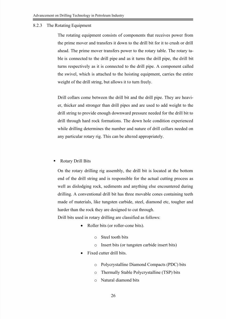
Whereas the roller bits are mostly applicable to water wells, diamond-
cutter bits are the most predominant nowadays in the petroleum business.
This is due to the extreme resistance of diamond to abrasive wear that has
made it possible to use shearing action of cutters for drilling. Hence, it can
cut through tough rocks quicker, reducing the cost of drilling for energy
resources.
Figure 9: Three Types of Bits used in Rotary Drilling
A – Steel tooth bit
B – Insert bit
C – Fishtail Polycrystalline Diamond Compact (PDC) bit
The choice of bit depends on the properties of the formations and drilling
technique.
8.2.4 The Circulating System
The circulating system is a continuous circulation of drilling fluid (mud)
down through the well throughout the drilling process. The rotary drilling
technique is designed to drill continuously without down time, hence the
need to get rock cutting off the well bore for the drill bit to have a clear
surface to drill on is just as important. The equipment needed for this cy-
clic system include; drilling fluid pumps, compressors, related plumbing
8/13/2019 Akpedeye Kelvin - hamk
http://slidepdf.com/reader/full/akpedeye-kelvin-hamk 34/62
Advancement on Drilling Technology in Petroleum Industry
28
fixtures, specialty injectors for the addition of additives to the fluid flow
stream, and separators (e.g. mud tank, pits or cyclone-type separator).
The main functions of the circulating system are:
Removal of cuttings from the bottom of the hole to the
surface. This exposes the drill bit to the uncut rock for-
mations for drilling to proceed as well as makes available
cuttings and samples for analysis to study geological
properties of rocks penetrated and to find the indication of
oil and gas in the formations.
Controlling hydraulic pressure in the hole by adjusting the
density of the mud to control formation fluids and to pre-
vent collapse of the well.
To cool and lubricate the working bit and drill stem.
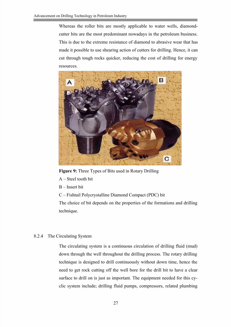
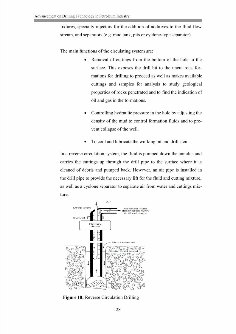
In a reverse circulation system, the fluid is pumped down the annulus and
carries the cuttings up through the drill pipe to the surface where it is
cleaned of debris and pumped back. However, an air pipe is installed in
the drill pipe to provide the necessary lift for the fluid and cutting mixture,
as well as a cyclone separator to separate air from water and cuttings mix-
ture.
Figure 10: Reverse Circulation Drilling

8/13/2019 Akpedeye Kelvin - hamk
http://slidepdf.com/reader/full/akpedeye-kelvin-hamk 35/62
Advancement on Drilling Technology in Petroleum Industry
29
Whereas in a conventional circulation system, the pumps force the drilling
fluid through the drilling pipe down and out through the drill bit. The fluid
(with cuttings) then flows up through the annulus to the surface of the
ground where it is cleaned of debris and pumped back down the hole.
The major difference between these two circulation systems is the en-
trance and exit points of drilling fluid respectively that are directly oppo-
site. However, either of both circulation system is an endless cycle that is
maintained as long as the drill bit is turning in the hole.
Advantages of the reverse circulation:
The reduction of velocity in the annulus reduces the possibility of
wall erosion.
The increase in velocity up the drill pipe provided fewer time lags
to the surface and less mixing of cuttings which enhance sam-
pling.
There is less possibility for formation damage by mud invasion
because water or very thin light mud is used.
Disadvantages of the reverse circulation:
Under-pressured geothermal fluids are prevented from entering
the hole for detection by temperature or chemistry change since
the annulus fluid level is at the surface.
The chemistry of geothermal fluid might be changed if they find
no space to enter the hole. Large amount of air usually scrubs out
carbon dioxide (CO2) and hydrogen sulphide (H2S).
Large amount of water can be required because there is very little
or no filter cake to prevent losses to permeable zones.
8/13/2019 Akpedeye Kelvin - hamk
http://slidepdf.com/reader/full/akpedeye-kelvin-hamk 36/62
Advancement on Drilling Technology in Petroleum Industry
30
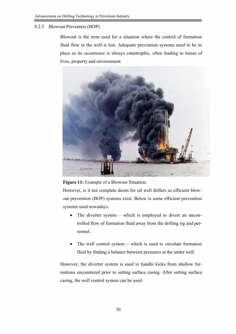
8.2.5 Blowout Preventers (BOP)
Blowout is the term used for a situation where the control of formation
fluid flow in the well is lost. Adequate prevention systems need to be in
place as its occurrence is always catastrophic, often leading to losses of
lives, property and environment.
Figure 11: Example of a Blowout Situation.
However, is it not complete doom for oil well drillers as efficient blow-
out prevention (BOP) systems exist. Below is some efficient prevention
systems used nowadays.
The diverter system – which is employed to divert an uncon-
trolled flow of formation fluid away from the drilling rig and per-
sonnel.
The well control system – which is used to circulate formation
fluid by finding a balance between pressures at the under well.
However, the diverter system is used to handle kicks from shallow for-
mations encountered prior to setting surface casing. After setting surface
casing, the well control system can be used.
8/13/2019 Akpedeye Kelvin - hamk
http://slidepdf.com/reader/full/akpedeye-kelvin-hamk 37/62
Advancement on Drilling Technology in Petroleum Industry
31
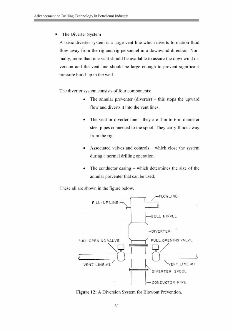
The Diverter System
A basic diverter system is a large vent line which diverts formation fluid
flow away from the rig and rig personnel in a downwind direction. Nor-
mally, more than one vent should be available to assure the downwind di-
version and the vent line should be large enough to prevent significant
pressure build-up in the well.
The diverter system consists of four components:
The annular preventer (diverter) – this stops the upward
flow and diverts it into the vent lines.
The vent or diverter line – they are 4-in to 6-in diameter
steel pipes connected to the spool. They carry fluids away
from the rig.
Associated valves and controls – which close the system
during a normal drilling operation.
The conductor casing – which determines the size of the
annular preventer that can be used.
These all are shown in the figure below.
Figure 12: A Diversion System for Blowout Prevention.
8/13/2019 Akpedeye Kelvin - hamk
http://slidepdf.com/reader/full/akpedeye-kelvin-hamk 38/62
Advancement on Drilling Technology in Petroleum Industry
32
The Well Control System
Like many other aspects of drilling operations, the problem of blowout
prevention increases in complexity especially nowadays that we have
more wells in deep waters; requiring the use of floating drilling vessels.
Well control problems associated with greatly reduced fracture gradient,
and the use of long subsea choke and kill lines in these deep water drilling
operations have to be managed.
For example, because of the relatively lengthy vertical subsea choke and
kill lines extending from the BOP stack at the sea floor, an increase circu-
lating frictional pressure loss results. This can cause a significant increase
in the overall pressure occurring in the well bore. In addition to that, is a
problem that results from rapid drop in hydrostatic pressure, especially
when circulating a gas kicks. When gas exits the large casing to a relative-
ly smaller diameter choke line, the hydrostatic pressure drops rapidly and
in order to maintain the bottom hole pressure, a corresponding increase in
surface choke pressure is needed. Choke manipulation and control be-
comes difficult during these periods and even much more difficult with in-crease in well depth.
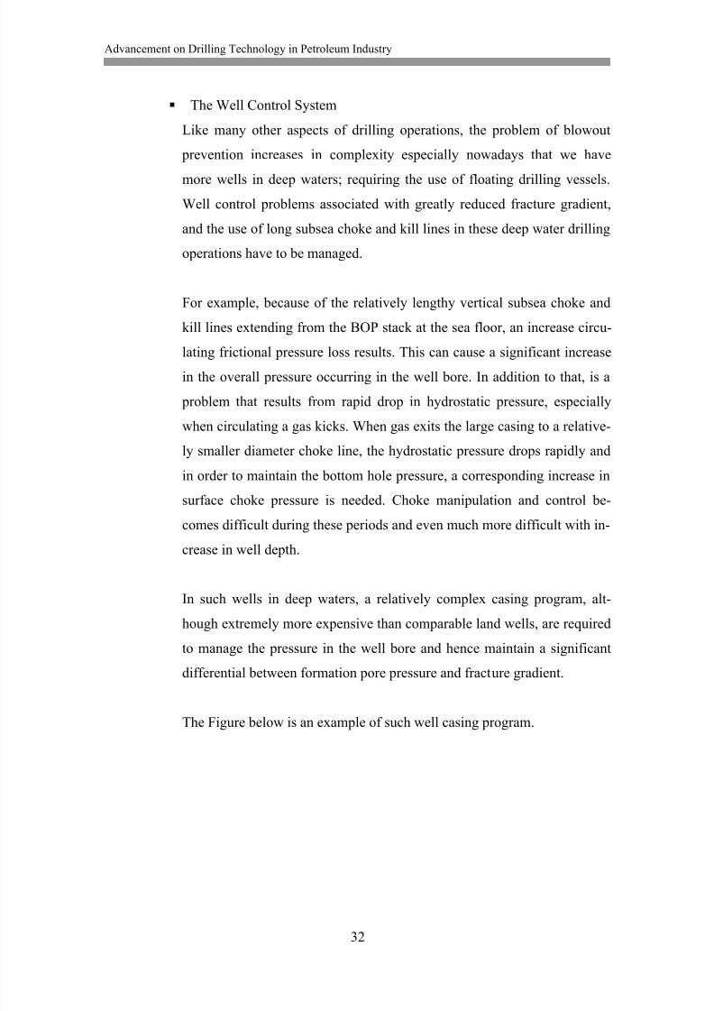
In such wells in deep waters, a relatively complex casing program, alt-
hough extremely more expensive than comparable land wells, are required
to manage the pressure in the well bore and hence maintain a significant
differential between formation pore pressure and fracture gradient.
The Figure below is an example of such well casing program.
8/13/2019 Akpedeye Kelvin - hamk
http://slidepdf.com/reader/full/akpedeye-kelvin-hamk 39/62
Advancement on Drilling Technology in Petroleum Industry
33
Figure 13: Example of Casing Program for Deep Water Well
8/13/2019 Akpedeye Kelvin - hamk
http://slidepdf.com/reader/full/akpedeye-kelvin-hamk 40/62
Advancement on Drilling Technology in Petroleum Industry
34
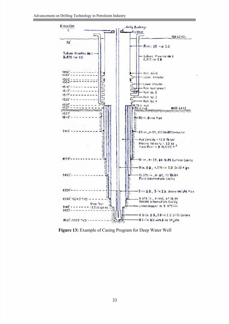
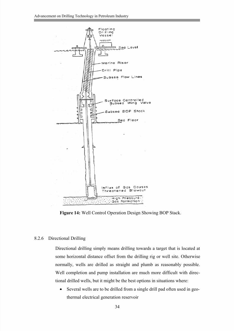
Figure 14: Well Control Operation Design Showing BOP Stack.
8.2.6 Directional Drilling
Directional drilling simply means drilling towards a target that is located at
some horizontal distance offset from the drilling rig or well site. Otherwise
normally, wells are drilled as straight and plumb as reasonably possible.
Well completion and pump installation are much more difficult with direc-
tional drilled wells, but it might be the best options in situations where:
Several wells are to be drilled from a single drill pad often used in geo-
thermal electrical generation reservoir
8/13/2019 Akpedeye Kelvin - hamk
http://slidepdf.com/reader/full/akpedeye-kelvin-hamk 41/62
Advancement on Drilling Technology in Petroleum Industry
35
To sidetrack or bypass a junk that cannot be fished off a hole. For ex-
ample, a twisted off drill pipe that cannot be fished off a hole.
To intersect a fault for increased production.
To drill parallel in close proximity to a fault to reduce the possibility
of fault movement shearing off a casing.
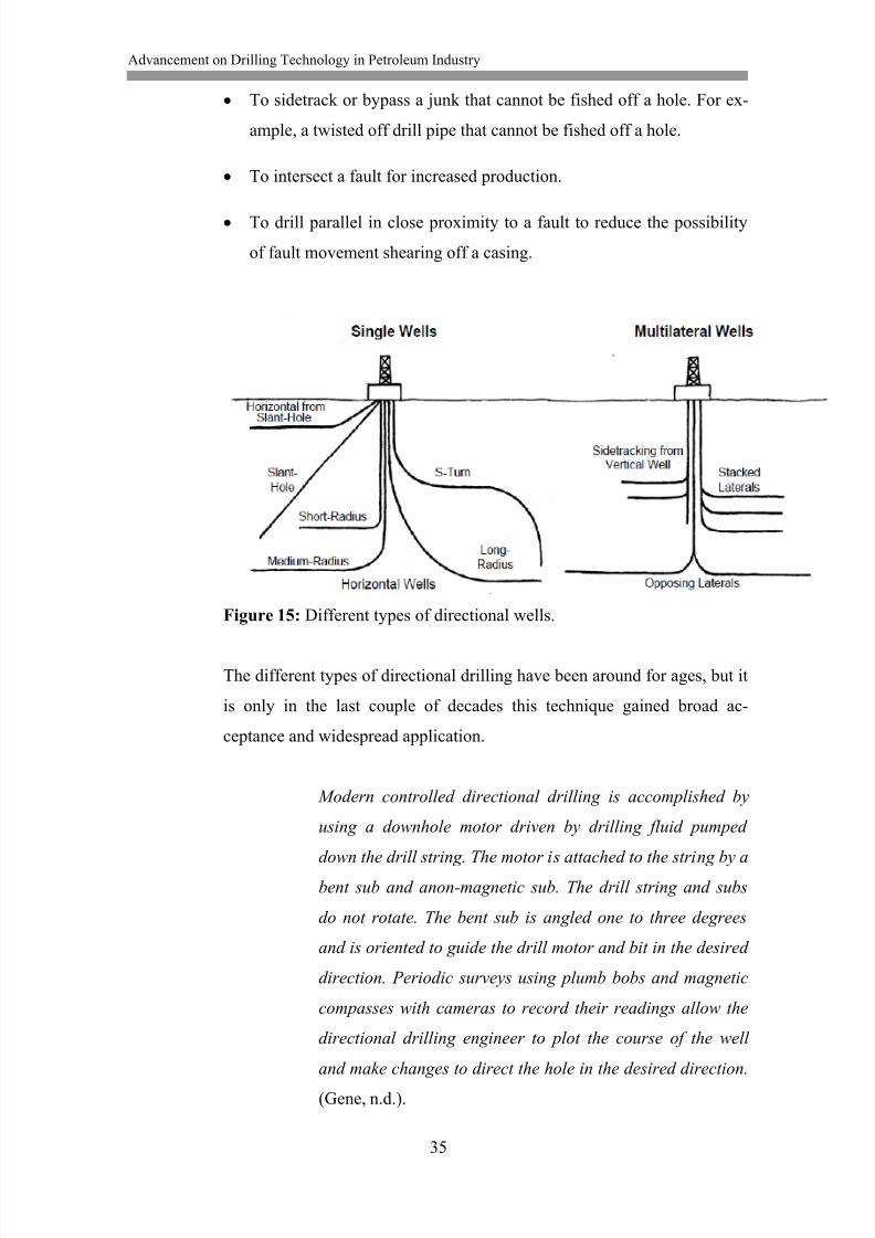
Figure 15: Different types of directional wells.
The different types of directional drilling have been around for ages, but it
is only in the last couple of decades this technique gained broad ac-
ceptance and widespread application.
Modern controlled directional drilling is accomplished by
using a downhole motor driven by drilling fluid pumped
down the drill string. The motor is attached to the string by a
bent sub and anon-magnetic sub. The drill string and subs
do not rotate. The bent sub is angled one to three degrees
and is oriented to guide the drill motor and bit in the desired
direction. Periodic surveys using plumb bobs and magnetic
compasses with cameras to record their readings allow the
directional drilling engineer to plot the course of the well
and make changes to direct the hole in the desired direction.
(Gene, n.d.).

8/13/2019 Akpedeye Kelvin - hamk
http://slidepdf.com/reader/full/akpedeye-kelvin-hamk 42/62
Advancement on Drilling Technology in Petroleum Industry
36
8.2.7 Drilling Fluids
In rotary drilling, drilling fluid is circulated through the system to remove
cuttings from the hole and performs several other functions. Be-
cause locations differ in local conditions, careful analysis should be made
before selecting what drilling fluid best suits what local drilling condi-
tions, bearing the maintenance of the drilling fluid in mind. Both the engi-
neer and the driller must be aware of the possible consequences of this se-
lection and maintenance.
The functions of drilling fluids include:
Cool and lubricate the bit and the drill string.
Clean the bottom of the hole beneath the bit.
Transport cuttings to the surface.
Suspend drill cuttings in the annulus when circulation is stopped.
Support the walls of the bore hole.
Control subsurface pressure.
Stabilize the bore hole.
To achieve these functions, the following side effects should be minimized.
Damage to subsurface formation, especially those that may be produc-
tive.
Reduction of penetration rate.
Swab and circulate pressure problems.
Loss of circulation.
Erosion of the borehole.
Swelling of the sidewalls of the borehole creating tight spots and/or
hole swelling shut.
8/13/2019 Akpedeye Kelvin - hamk
http://slidepdf.com/reader/full/akpedeye-kelvin-hamk 43/62
Advancement on Drilling Technology in Petroleum Industry
37
Sticking of the drill pipes against the walls of the hole.
Retention of undesirable solids in the drilling fluid.
Wear on the pump parts.
A good drilling fluid has the following characteristics:
Lubricity
Velocity
Viscosity
Density
Gel Strength
Filtrate control
Drilling fluids fall into one of three general classes:
Water based
Air based
Oil based
In today‟s petroleum drilling, mud is the most commonly used drilling flu-
id because it possesses most of the characteristics listed above. It is classi-
fied under the water based class, as water that is re-circulated can be seen
as very thin mud containing suspended particles of drilled cuttings. How-
ever, polymer fluids – classified under oil based, and foam – classified un-
der air based are employed in some drilling conditions.
Drilling Mud
Modern drilling mud is primarily mixtures of bentonite (sodium montmo-
rillonite) and water plus special additives needed to modify its properties
to meet changing hole conditions or counteract changes previously made
by the driller. Normally, when bentonite is added to water, an increase in
the density and viscosity is noticed. Additives, such as organic polymers,
dispersants, wetting agents, weighting agents, thinner and lubricants, are
8/13/2019 Akpedeye Kelvin - hamk
http://slidepdf.com/reader/full/akpedeye-kelvin-hamk 44/62
Advancement on Drilling Technology in Petroleum Industry
38
then added to improve gelation, lubricity, filtration and other properties,
thus making it a suitable drilling fluid.
As the mud is used, it gradually losses its standard physical properties, as
it carries cuttings from the hole. Hence, regular measurements are needed
to keep these properties in check in order to improve performance. Some
of these properties include:
DENSITY
Mud density or mud weight usually expressed in pounds per gal-
lon (ppg) is measured with a mud balance or a balance beam. An
increase in density results in relative increase in cutting carrying
capacity, as well as increase in borehole pressure and thus reduce
caving in and formation fluid flow into the hole. Mud density in-
crease, on the other hand, decreases settling rate in the mud pit
and may result in loss of circulation as it increases the flow of
drilling mud into the formation. Generally, 9ppg is the maximum
recommended.
Density can be increased by the addition of barite – a weighting
agent. Hydrostatic pressure can be calculated with:
P = 0.052ed (1)
Where
P = hydrostatic pressure (psi)
e = density (ppg)
d = depth (ft)
VISCOSITY
Mud viscosity, expressed in seconds per quart (s/qt), is a measure
of its ability to carry cuttings up the hole, drop them in the mud
pit and to form a gel. In fields, it is measured by measuring the
time it takes a measured amount of mud, usually one quart, to
flow through a standard Marsh funnel. This is its funnel or appar-
ent viscosity; different from its true viscosity. At 21oC, water has
a funnel viscosity of 26s/qt and 32 to 38s/qt is a very typical
range for a good drilling mud.
8/13/2019 Akpedeye Kelvin - hamk
http://slidepdf.com/reader/full/akpedeye-kelvin-hamk 45/62
Advancement on Drilling Technology in Petroleum Industry
39
Although viscosity is affected by density and the type of sus-
pended solids, the true viscosity changes only a little compared
with changes in its funnel viscosity. Mud viscosity is adjusted by
varying the amount of bentonite and water or by adding polymers
to thicken or phosphate to lighten the fluid.
SAND CONTENT
The volume of sand in the drilling mud should be kept to its beer-
iest minimum as this affects mud density, viscosity, bit life, drill-
ing rate and causes formation damage, wear of pumps, swivels
and other equipment.
Sand content is measured by carefully washing a measured vol-
ume of mud on a 200 mesh screen and afterwards, pouring the
materials held on the screen on a cone shaped graduated contain-
er. The desired maximum limit is 2% by volume. Regular meas-
urement pays out on the long run.
FILTER CAKE
Filter cakes are clay platelets built up on the formation to reduce
fluid loss into the formation. Because the drilling mud in the an-nulus is under pressure, some water filters through these filter
cakes in some occasions causing water loss. In extreme cases, the
whole mud goes through resulting in mud loss.
A standard API filter press is used to measure filter cake thick-
ness and water loss. A compressor supplies gas pressure of
100psi to a set up of filter paper supported in a mud filled stand-
ard cell. This is kept for 30minutes. Afterwards, the amount of
water that passed through the filter paper is measured as well as
the buildup of the filter cake in the paper. Desirable properties are
15cm3/30min of water and 2/32in thickness of filter cake.
GELLING
This is a property of a bentonite and water mixture that allows it
to be fluid when stirred but when left to stand; it begins to stiffen
or gels and becomes fluid again when stirred. This helps to sus-
8/13/2019 Akpedeye Kelvin - hamk
http://slidepdf.com/reader/full/akpedeye-kelvin-hamk 46/62
Advancement on Drilling Technology in Petroleum Industry
40
pend cuttings during non-circulation periods. Gel strength is pro-
gressive and can increase to a strength that becomes almost im-
possible to remove. What we do not want to happen is for our
drilling mud to gel and set in a potential geothermal producing
zone. It can be very undesirable in such situation.
For example, when a circulation is loss or reduced, the mud con-
tinues to flow into the formation until the hydrostatic and for-
mation pressures regain its balance. Once these pressures are bal-
anced and circulation is regained, the mud in the formation stops
flowing and begins to gel. Except sufficiently diluted by for-
mation water, the mud gels and sets to a strength that affects pro-
duction if that were a productive zone.
Gelling can be used to stop loss circulation by adding more ben-
tonite and pumping it down hole. With the bit pulled to a safe dis-
tance, the mud is allowed enough time to gel and set and drilling
continues slowly afterwards. Problem is if this is a potential pro-
duction zone, it is lost as it is almost impossible or very expen-
sive to remove.
LOST CIRCULATION AND LOST CIRCULATION
MATERIALS (LCM)
Lost circulation, sometimes referred to as lost return, is the loss
of drilling fluid from the borehole through cracks, crevices or po-
rous formations. This can either be partial or complete if part or
all the fluid, respectively, fail to return to the surface. When cir-
culation is lost, it is obvious that the drilling fluid can no longer
perform its transporting cuttings up the well function, leading to
blind drilling. If these cuttings remain in the hole, they will pack
around the drill string above the bit resulting in stuck pipe, and
possibly loss of the bit, drill collars, part of the string or maybe
the hole.
However, if the formation is very porous – with large cracks or
crevices, the fluid may carry cuttings away with itself into the
formation. None the less, the drillers have no assurance that this
8/13/2019 Akpedeye Kelvin - hamk
http://slidepdf.com/reader/full/akpedeye-kelvin-hamk 47/62
Advancement on Drilling Technology in Petroleum Industry
41
is the case. On the other hand, a continuous loss of the fluid may
reduce the fluid level below the surface, resulting in partial or
complete loss of fluid pressure needed to stabilize the hole wall.
This in turn can cause cave-ins, another cause of stuck pipe that
can lead to loss of equipment in the hole.
Other problems associated with loss of circulation include:
Loss of expensive fluid components
Loss of drilling time
Added cost of expensive lost circulation materials to keep
losses from plugging possible production zones
Cementation problem
Proper planning and rig operations are important in order to re-
duce the possibility of this occurring. Some of these techniques
include:
The use of nearby well logs and geological information
and carefully planning the hole and casing program.
Treating the well bore gently. This involves; raising and
lowering of the drill strings and casing slowly without
spudding, starting fluid pumps at slow rates and increase
slowly, maintaining fluid velocity in the annulus at the
lowest rate to assure cuttings removal, and avoiding too
fast drilling to prevent overloading the annulus with cut-
tings.
Making frequent measurements of mud properties to
maintain minimum weight, viscosity and filtration.
Lost Circulation Materials (LCM) are materials used to bridge
across openings or pores in the formation and provided a founda-
tion for the building of filter cakes. Any piece of material can do
this job including; groundnut shells, sawdust, hog hair, etc.
Although, organic materials can do a better job compared with
inorganic materials – such as mica flakes, their use is prohibited
8/13/2019 Akpedeye Kelvin - hamk
http://slidepdf.com/reader/full/akpedeye-kelvin-hamk 48/62
Advancement on Drilling Technology in Petroleum Industry
42
because they promote undesired organic growth or degrade water
quality or both. The best materials are thought to be a mixture of
flake and fibre
.
Air-Based Fluids
Like the name, this is drilling with air. The simplest form is the use of dry
air. It becomes more complicated when there is the need to convert the dry
air to either mist or foam in situations where water is encountered. The
lifting capacity of air and the volume requirement are two very important
factors to consider. Where the former is directly proportional to its density
and annular velocity, the later is directly related to the well depth. As the
hole depth increases, the air velocity is reduced because of increased
weight of cuttings supported and pressure build-up due to friction. With
the need to increase velocity to compensate for the loss, excessive velocity
can lead to erosion of softer formations which in turn will require more air
to maintain adequate velocity in the increased annular space. On the other
hand, excessive air pressure can lead to air loss just like lost circulation in
water-based drilling mud, resulting in stuck tools as cuttings pack around
the drill stem above the bit.
Air drilling is at its best when drilling on consolidated formations. This is
so because it eliminates the danger of caving, possibly resulting in stuck a
tool that is common with its application on unconsolidated formations. Air
loss to the formation, equally resulting in stuck tools, can also be as a re-
sult of the formation of mud rings in the drill pipe and hole wall, resulting
in pressure build up and reduction in velocities. These mud rings are
formed when small amounts of water mixes with cuttings and dusts espe-
cially with Shale.
Besides the use of dry air, air mist and foams are other fluids applicable to
air-based drilling.
8/13/2019 Akpedeye Kelvin - hamk
http://slidepdf.com/reader/full/akpedeye-kelvin-hamk 49/62
Advancement on Drilling Technology in Petroleum Industry
43
AIR MIST DRILLING
Air mist drilling is a technique developed to increase the density
of air column, resulting in pressure increase at the bottom of the
hole. Air mist is a drilling fluid gotten by adding little amount of
water to the surface plus wetting agents that help remove mud
rings and controls dusts. This technique is effective if the amount
of water entering from the formation is kept as small as between
15 to 25 gpm.
FOAM DRILLING
In contrast to the general knowledge of foam composition, drill-
ing foam is composed of a small amount of water and large
amount of air. It is made by injecting water and additives into the
air stream by a metering pump. Depending on drilling require-
ments, one of stable foam, stiff foam or wet foam can be used.
Stable foam is made by adding surfactants and sometimes poly-
mers and clay – to increase the viscosity and density. Surfactants
are additives that:o Provides the ability to lift large volumes of water
o Reduce air volume requirements
o Provides greater solids carrying capacity
o Reduced erosion of poorly consolidated formations.
Stiff foam – made with polymers (3 to 6lb/100gal) or bentonite
(30 to 50lb/100gal) and 1 to 2% surfactant, can be used with an-
nular velocities as low as 50 to 100ft/min. However, with higher
annular velocities of up to 1000ft/min, wet foam may be used.
Wet foams are made with 0.25% surfactants only and no other
additive.
Air, being a compressible fluid, follows the ideal gas laws. This
holds for the relationship between pressure (P), temperature (T)
and Volume (V) for all types of air-based fluids drilling. Below is
8/13/2019 Akpedeye Kelvin - hamk
http://slidepdf.com/reader/full/akpedeye-kelvin-hamk 50/62
Advancement on Drilling Technology in Petroleum Industry
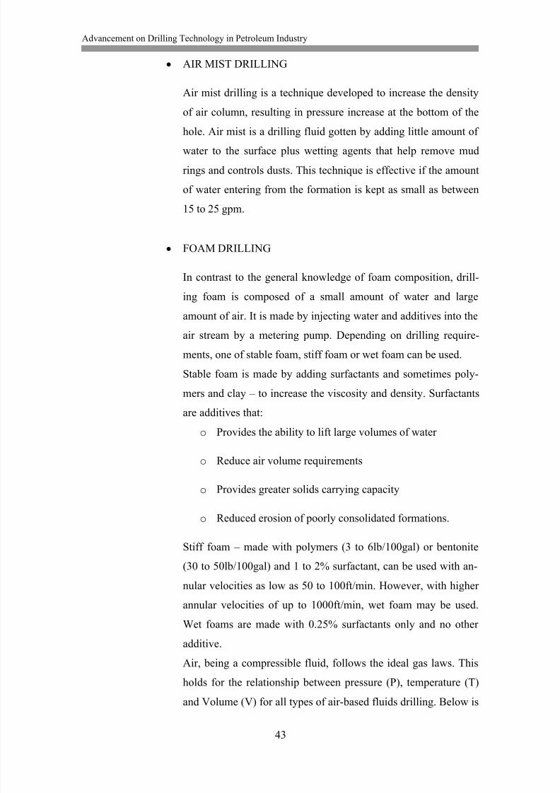
44
a figure showing these relationships and components of air rotary
circulating system.
Figure 16: Air-based fluid rotary circulation system
Pressure and temperature are high and volume is low as the fluid goes into
the air feed line and down through the drill pipe. At the bit, a rapid expan-
sion occurs with a drop in pressure and temperature. Expansion continues
until the pressure at the bit equals the pressure caused by resistance to
flow in the presence of cuttings and water load.
Air-based fluid in rotary drilling has the following advantages over water-
based fluids.
Higher penetration rates, especially in hard rock.
Easy detection of aquifers and estimation of potential flow rates.
Reduced formation damage.
Longer bit life.
8/13/2019 Akpedeye Kelvin - hamk
http://slidepdf.com/reader/full/akpedeye-kelvin-hamk 51/62
Advancement on Drilling Technology in Petroleum Industry
45
No water (or very little) required for drilling.
Better formation samples.
On the other hand, the major disadvantage of air-based fluids is associated
with the fact that all air-systems bring the water to the surface. This pre-
sents disposal problems and the danger of dealing with hot water. Other
disadvantages include:
Higher cost of equipment and fuel cost for driving compressors.
Dust.
Noise of compressors and blooie exhaust.
Polymer Fluids
Polymer fluids are the third class of drilling fluid. They can be either natu-
ral or synthetic.
Natural polymers – Most of them are biodegradable while others
are broken down easily by oxidizers such as weak acids.
Synthetic polymers – Inorganic or organic. Organic polymers are
not very encouraged as they possess the potential of pollution.
Polymers have no gel strength but they provides high viscosity that is re-
quired to carry cuttings up the hole and drop them in the mud pit just as ef-
fective. To a very great extent, problems associated with bentonite, due to
gelling, are eliminated in low-temperature geothermal wells with the ap-
plication of polymer fluids. Fortunately, polymers lack of gelling is the
reason for this.
However, a major setback with the use of polymer drilling fluids is due to
the fact that they are easily broken down. Geothermal fluids normally con-
tain chemicals and dissolved gases that may react with polymers, especial-
ly in high temperature regions. These reactions can either reduce viscosity
by breaking the long polymeric molecule or form a thick gel by cross link-
ing the molecules.
8/13/2019 Akpedeye Kelvin - hamk
http://slidepdf.com/reader/full/akpedeye-kelvin-hamk 52/62
Advancement on Drilling Technology in Petroleum Industry
46
8.2.8 Advantages of Rotary Drilling
Rotary drilling has the following advantages.
It can drill through most rock formations.
Water and mud support unstable formations
It has a high penetration rate.
Operation is possible above and below the water-table.
Possible to drill to depths of over 14,000ft
Easier directional drilling.
Possible to use compressed air flush.
8.2.9
Disadvantages of Rotary Drilling
Rotary drilling has the following disadvantages.
It is capital intensive.
Often requiring pumping water in large volume.
Often requires mud mixing equipment and dug pits or metal tanks for
circulation.
It requires fundamental knowledge of bentonite and additives needed
to achieve adequate penetration rates and stabilize formations.
There can be problems with boulders.
Rig requires careful operation and maintenance.
It is more difficult to identify water bearing zones, especially in low
flow operations.
8/13/2019 Akpedeye Kelvin - hamk
http://slidepdf.com/reader/full/akpedeye-kelvin-hamk 53/62
Advancement on Drilling Technology in Petroleum Industry
47
Loss circulation zones can cause aquifer contamination and dramati-
cally increase bentonite cost.
Mud may plug aquifers and cause decreased production.
Disposal of mud after hole is drilled can be inconvenient and expen-
sive.
It is often difficult to work with mud in freezing temperatures.
Driller still bears the risk of the hole collapse or swell, resulting in
possible loss of drill string or jamming of casing during installation.
8.3 Laser Drilling Technique
The setting is not a complicated one, just like in laser welding. A very im-
portant aspect of this is the simplicity in pointing the laser head to the spot
to be drilled. In petroleum and gas wells, as the hole depth increases, all
that is needed is a corresponding increase in the length of drill pipes in or-
der to get the laser head close and pointed to the uncut surface at the bot-
tom of the well for boring to continue.
However, just like there is no rotary drilling technique without a circulat-
ing system and drilling fluids, a purging system plays a similar role in la-
ser drilling technique. The purging system provides a transparent medium
for the laser to pass through, cleans the hole of cuttings, and move molten
rock into the fractures to seal them as well as sealing the wall of the well-
bore.
Reflection, scattering and absorption characterize the transfer of radiant
energy (laser) to solid rocks in order to destroy them. Amongst them, ab-
sorption is the process by which heat is collected by the rock; which even-
tually results in destroying it (Graves and O‟Brien 1998). Scattering and
reflection represent energy that is not absorbed by the rock or energy loss-
es in the system. Therefore, for the feasibility of laser drilling,
Graves and O‟Brien (1998) outlined the following criteria:
8/13/2019 Akpedeye Kelvin - hamk
http://slidepdf.com/reader/full/akpedeye-kelvin-hamk 54/62
Advancement on Drilling Technology in Petroleum Industry
48
Low reflectivity of rocks result in good coupling of laser radiation
with rocks.
Deep penetration of laser energy into rock resulting in volumetric ab-
sorption of laser energy.
Low thermal conductivity of rocks resulting in effective heating.
Major advantages of laser drilling over conventional drilling include:
It drills 100 times faster
It makes more precise holes
Reduces downtime due to dull bits
Eliminates waste created by drilling mud (cuttings vaporize)
It creates a ceramic surface that seals the wall of the well
It eliminates influx/out-flux of fluids hence formation damage is elim-
inated as well.
It is much more economical both in saving time and reducing extra
cost of employing, for example steel wall casing.
8/13/2019 Akpedeye Kelvin - hamk
http://slidepdf.com/reader/full/akpedeye-kelvin-hamk 55/62
Advancement on Drilling Technology in Petroleum Industry
49
9 DISCUSSION
This entire section is based on recent experiment works undertaken with the aim of
applying laser technology in drilling and perforating oil and gas wells. Different
rocks types were exposed to lasers for certain time interval, and inferences were
made on rate of penetration (ROP), specific energy (SE), and the effect of lasers on
permeability on the formation.
Graves and O‟Brien (1998) conducted an experiment to determine the feasibility of
MIRACL (Mid Infrared Advanced Chemical Laser) for drilling and perforating
wells. MIRACL is a US Army‟s continuous wave laser with a wavelength of 3.8µm
and a power output of 5 – 12 kW. A 6-inch and a 2-inch diameter holes were drilled
on two 12 by 12 by 3-inches samples of 9 Darcy dry Sandstone. On the first slab,
the 6-inch diameter hole was drilled to determine the amount removed by a full la-
ser beam, for drilling purpose. The laser was directly pointed at the slab and a 2.5-
inch deep hole was produced after only 4.5s. This result is an equivalent rate of
penetration (ROP) of 166ft/h. On the other slab, the 2-inch diameter hole was
drilled horizontally with an output power of 500kW. This was to confirm the feasi-
bility of laser for perforation purpose. The rock was exposed to the laser for 2s and
a 6-inch deep hole was created; which is equivalent to a ROP of 450ft/h. Permeabil-
ity tests were equally conducted on the slab before the experiment and around the
hole after the experiment and no change was noticed.
Graves et al. (1999) conducted an experiment on Sandstone, Limestone, Shale, Salt
and Granite with the use of COIL (Chemical Oxygen-Iodine Laser) with an aim to
determine the least specific energy (SE) needed to destroy varying rock types.
COIL is a US Air Force continuous wave, with power between 5 – 10kW and
wavelength of 1.315µm, laser designed to track and destroy missiles at 31mile ra-
dius. Comparing that distance to a petroleum well that is approximately 3miles
deep, it was a welcome candidate. 0.25-inch diameter holes were created on each
specimen irradiated for 8s and the SE‟s were determined. For three different power
levels (100, 50 & 35%), the SE determined for the rock specimen range from 10 –
40kJ/cm3. However, the salt specimen used the lease SE at 100% power level
8/13/2019 Akpedeye Kelvin - hamk
http://slidepdf.com/reader/full/akpedeye-kelvin-hamk 56/62
Advancement on Drilling Technology in Petroleum Industry
50
whereas limestone used the least for other power levels. On the other hand, Shale
consistently used the largest amount of SE. However, a more recent experiment
showed that limestone SE is greater than shale. (Gahan et al, 2001). The explana-
tion for this was due to the fact that a lighter coloured limestone was used and its
reflective property was correspondingly higher resulting in less energy absorption.
The relationship between SE and ROP was also determined for the five rock speci-
men. They are inversely proportional, i.e., as the SE increases, the ROP decreases.
In addition, Graves et al. (1999) gave an account on the effect of fluid saturation on
SE. Cores were saturated with fresh water, brine, oil, and gas and the test showed
that a little increase in the SE was needed to penetrate the saturated cores.
Hole penetration limitation test was performed to determine the effect of hole depth
and vapour contamination in the wellbore on the ROP (Graves et al. 1999). Rock
specimen were lased for 3, 6, 9, 12, & 15s and it was found that the greater the irra-
diation time, the greater the SE. Gahan et al (2001) equally concluded on this direct
proportion relation between exposure time and SE required when samples of rocks
were lased for 0.5, 1.0, & 1.5s with Nd:YAG pulsed laser. Graves et al (1999)
pointed that plasma screening perhaps is a factor. Plasma screening is the formation
of liquid or gas that leads to a change in the atmospheric condition in the hole. Theyconcluded that an increase in exposure time consumes laser energy as it allows for
the development of melted rock that acts as a barrier between the laser and the un-
cut surface of the hole bottom (rock).
In conventional drilling system, there are many factors that determine the rate at
which the borehole is drilled. They include; weight-on-bit (WOB), mud circulation
rate, rotary speed, hydraulic horsepower bit design and hold size. With laser drill-
ing, this rate may only depend on the delivered power and the hole size (Graves et
al 1999) thus eliminating the complexity of the current drilling technique. Dr.
Claude (May 10, 2006) in an interview on History Channel pointed out that in
about ten years‟ time, laser drilling will probably replace all oil and gas well drill-
ing technique. He explained that lasers can penetrate, melt and vaporize any rock
material.
8/13/2019 Akpedeye Kelvin - hamk
http://slidepdf.com/reader/full/akpedeye-kelvin-hamk 57/62
8/13/2019 Akpedeye Kelvin - hamk
http://slidepdf.com/reader/full/akpedeye-kelvin-hamk 58/62
Advancement on Drilling Technology in Petroleum Industry
52
11 REFERENCES
Dr. Brantly, J. E. 1971. History of Oil Well Drilling. Houston, London, Paris, To-
kyo: Gulf Publishing Company.
Dr. Claude B. Reed. 2006. Laser Rock Drilling. History Channel. Interview.
1.5.2006
http://www.ne.anl.gov/facilities/lal/DemoMovies/laser_well_drilling/LRD_Hist_Ch
annel.html. Referenced 15.12.2009
Dr. Claude B. Reed. 2009. Laser Oil and Gas Well Drilling. Argonne National La-
boratory.
http://www.ne.anl.gov/facilities/lal/laser_drilling.html. Referenced 02.12.2009
Dr. Reimer, P. 2009. World Petroleum Council. http://www.world-petroleum.org.
Referenced 13.01.2010.
Erik M. Molvar, Dr. Rickey P., Walter K. Merschat. 2003. Drilling Smarter: Using
Directional Drilling to Reduce Oil and Gas Impact in the Intermountain West
http://www.voiceforthewild.org/blm/pubs/DirectionalDrilling1.pdf . Referenced
27.12.2009.
Foremost Industries LP. 2003. Benefits of Dual Rotary Drilling in Unstable Over-
burden Formations. http://www.foremost.ca/pdf/en/dr_benefits.pdf. Referenced
07.01.2010
Gahan B. C., Richard A. Parker, Gas Technology Institute; Batarseh S., Colorado
School of Mines; Humberto Figueroa, PDVSA-Intevep, S.A.; Claude B. Reed, Zhi-
yue Xu, Argonne National Laboratory. 2001. SPE 71466. In: SPE Annual confer-
ence and Exhibition. New Orleans, Louisiana, 30.09 – 3.10.2001.
8/13/2019 Akpedeye Kelvin - hamk
http://slidepdf.com/reader/full/akpedeye-kelvin-hamk 59/62
Advancement on Drilling Technology in Petroleum Industry
53
Gene C. n.d. Drilling and Well Construction.
http://www.osti.gov/geothermal/servlets/purl/895127-cWjqee/895127.pdf. Refer-
ence 20.01.2010.
Graves, R. M., and O'Brien, D. G. 1998. StarWars Laser Technology Applied to
Drilling and Completing Gas Wells.
http://www.ne.anl.gov/facilities/lal/Publications/Laser%20well%20drilling/SPE%2
049259.pdf. Referenced 08.02.2010
Graves, R. M., and O‟Brien, D. G., O‟Brien, E. A. 1999. StarWars Laser Technolo-
gy for Gas Drilling and Completion in the 21st Century. SPE 56625-MS Journal.
Irfan K., Mohit K., Nakul M., Vickey C., Nikhil K., Anand S., SPE, Maharashtra
Institute of Technology, Pune. 2009. SPE Annual Conference Exhibition, Offshore
Europe. 8 – 11.09.2009.
John H. Berry. n.d. Drilling Fluids Properties & Functions.
http://www.cetco.com/CDP/Bentonite/Properties%20of%20a%20Drilling%20Fluid
.pdf. Referenced 20.01.2010.
Kurts Prengling, DeGolyer, MacNaughton and McGhee, Eugene A. Stephenson,
University of Kansas. 1940. In: Drilling and Production Practice. API 40-064
Journal.
Mustafiz, S., Bjorndalen, N. and Islam, M. R. 2004. Lasing into the Future: Poten-
tials of Laser Drilling in the Petroleum Industry.
http://dx.doi.org/10.1081/LFT-200034067. Referenced 09.01.2010
Oliver Kuhn. n.d. Ancient Chinese Drilling.
http://www.cseg.ca/publications/recorder/2004/06jun/06jun-ancient-chinese-
drilling.pdf . Referenced 20.12.2009
Petroleum 2009. Encyclopedia Britannica.
8/13/2019 Akpedeye Kelvin - hamk
http://slidepdf.com/reader/full/akpedeye-kelvin-hamk 60/62
Advancement on Drilling Technology in Petroleum Industry
54
http://www.britannica.com/EBchecked/topic/454269/petroleum/50714/Oil-traps.
Referenced 20.11.2009
Tanaka S., Okada Y. and Ichikawa Y. 2005. Offshore Drilling and Production
Equipment. http://www.eolss.net/ebooks/Sample%20Chapters/C05/E6-37-06-
04.pdf. Referenced 28.11.2009.
The American Oil & Gas Historical Society. 2006. Making Hole.
http://www.aoghs.org/pdf/septwebsite.pdf. Referenced 01.12.2009
The Department of Environmental Protection, 2009. Oil and Gas Well Drilling and
Production in Pennsylvania.
http://www.elibrary.dep.state.pa.us/dsweb/Get/Document-74407/5500-FS-
DEP2018.pdf. Referenced 25.01.2010.
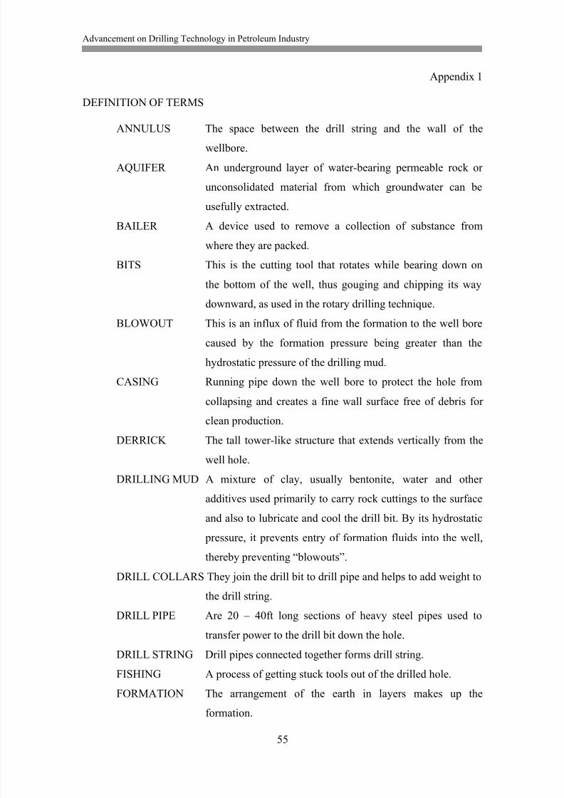
8/13/2019 Akpedeye Kelvin - hamk
http://slidepdf.com/reader/full/akpedeye-kelvin-hamk 61/62
Advancement on Drilling Technology in Petroleum Industry
55
Appendix 1
DEFINITION OF TERMS
ANNULUS The space between the drill string and the wall of the
wellbore.
AQUIFER An underground layer of water-bearing permeable rock or
unconsolidated material from which groundwater can be
usefully extracted.
BAILER A device used to remove a collection of substance from
where they are packed.
BITS This is the cutting tool that rotates while bearing down on
the bottom of the well, thus gouging and chipping its way
downward, as used in the rotary drilling technique.
BLOWOUT This is an influx of fluid from the formation to the well bore
caused by the formation pressure being greater than the
hydrostatic pressure of the drilling mud.
CASING Running pipe down the well bore to protect the hole from
collapsing and creates a fine wall surface free of debris for
clean production.
DERRICK The tall tower-like structure that extends vertically from the
well hole.
DRILLING MUD A mixture of clay, usually bentonite, water and other
additives used primarily to carry rock cuttings to the surface
and also to lubricate and cool the drill bit. By its hydrostatic
pressure, it prevents entry of formation fluids into the well,
thereby preventing “blowouts”.
DRILL COLLARS They join the drill bit to drill pipe and helps to add weight to
the drill string.
DRILL PIPE Are 20 – 40ft long sections of heavy steel pipes used to
transfer power to the drill bit down the hole.
DRILL STRING Drill pipes connected together forms drill string.
FISHING A process of getting stuck tools out of the drilled hole.
FORMATION The arrangement of the earth in layers makes up theformation.
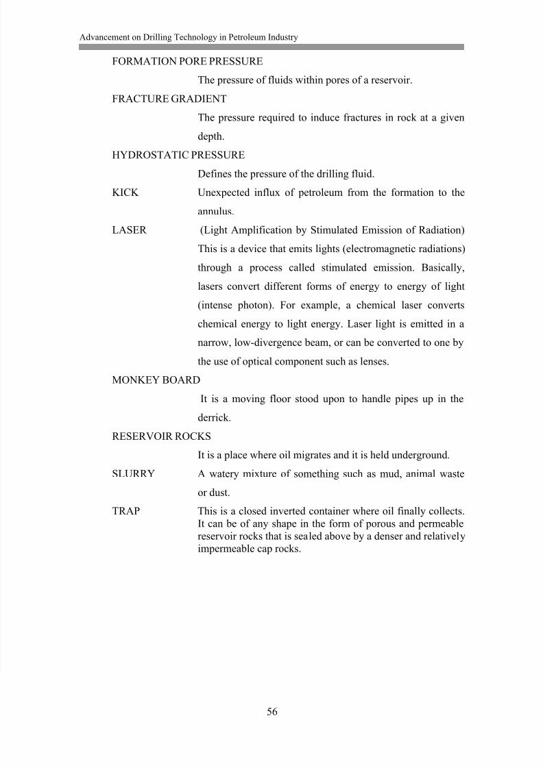
8/13/2019 Akpedeye Kelvin - hamk
http://slidepdf.com/reader/full/akpedeye-kelvin-hamk 62/62