ご注文をいただくにあたって ordering informations...2010/10/18 ·...
TRANSCRIPT

製品をより正しく、安全にご使用いただくために、さらに詳細な特性・仕様をご確認いただける納入仕様書をぜひご請求ください。記載内容は、改良その他により予告なく変更する場合がありますので、あらかじめご了承ください。
Explanations of Part NumberProduct par t numbers are created as shown in below. Although the composition may change slightly depending on the series, please specify the part number in this way when ordering.
(1)Ferrite material(2)Core series(Core style)(3)A part of core dimensions(4)Suffix code for core shape(5)AL value (Z: Without air gap core When required gap length: Indicated the dimensional value in mm)(6)Optional construction code (B: With air gap for both side∗ M: Mirror like surface lapping Regular core: Non indication) ∗Regular cores are gapped one side only.
(1)Ferrite material(2)Core series(for R, UU,UT and ET )(3)Core dimensions(Example: OD./ID./TH. for R core)(4)Suffix code for core shape(5)Optional construction code E: Epoxy coating P: Paraxylylene coating
When OrderingPlease contact our company, regarding whether or not safety regulations are applicable to the product, in order to avoid accidents or misuse, and to ensure full understanding of the specifications and characteristics of the product. When there is an applicable safety related regulation, please request a “specifications” document and read carefully to fully understand the contents.
The characteristic standards for each product listed in this catalog also show approximate values for some products. Changes may also be made without notification for product improvements, etc. Before using the product, please contact our company to confirm the information.
This catalog shows our standard products. For the characteristics of the materials used, and core shape of products other than these, please do not hesitate to contact our company.
製品の呼称法当社では、つぎのように製品名を構成しております。製品のシリーズにより多少構成要素が異なりますが、ご注文の際にはこれら呼称法によりご指定ください。
(1)フェライト材質名(2)コアのシリーズ名(コア形状)(3)コア寸法(4)形状補助記号(5)AL value
( G a p な し の 場 合 は Z、 G a p 寸法 を 指 定 の 場 合 は 寸 法 値 mmで表します )
(6)特殊加工記号 (B:両コアに Gap加工*、M:鏡面研磨 標準製品は表示がありません ) *標準製品の Gap加工は片側コアのみです
(1)フェライト材質名(2)コアのシリーズ名(R、UU、UT、ET)(3)コア寸法(Rコア:外径/内径/厚さ)(4)形状補助記号(5)特殊加工記号 E:エポキシ樹脂コーティング P:パリレン樹脂コーティング
ご注文にあたって製品の特性、仕様をご理解いただき、誤った使用による事故の発生を防止するために、製品のご使用に際しては安全性関連規定の有無について、当社までお問い合わせください。該当する製品の場合は、注意事項を記載した「納入仕様書」をご請求の上、内容をご確認ください。
本カタログに記載されている製品の特性規格には、各製品の概略値を示したものもあります。また、改良その他により予告なく変更する場合があります。ご使用にあたっては改めて、当社営業所を通じ、ご仕様のご確認をお願いいたします。
本カタログには、当社の標準品を掲載しております。掲載製品以外の材質特性・コア形状についてご希望がございましたら、当社営業所へお申しつけください。
[例 -1] MB3 EER - 28.5 B - 100 - Example-1 (1) (2) (3) (4) (5) (6)
[例 -2] MA055 R - 25/15/12 A - Example-2 (1) (2) (3) (4) (5)
ご注文をいただくにあたってOrdering Informations

FERRITE MATERIALS FOR POWER SUPPLY
低パワーロス材標準材質特性Low Power Loss Material Characteristics
標準材質特性Material Characteristics
材質名 Material MB1 MB3 MB4 MBT1
初透磁率 µ i 23°C 2000±25% 2500±25% 2500±25% 3400±25%Initial permeability
実効飽和磁束密度(1200A/m)23°C 510 510 520 510
Saturation flux density at 1200A/mBms (mT) 60°C 470 450 470 460
100°C 420 390 400 390
実効飽和残留磁束密度23°C 310 130 130 90
RemanenceBrms (mT) 60°C 170 90 88 70
100°C 80 55 54 60
実効飽和保磁力23°C 14.0 14.3 12.7 9.0
CoercivityHcms (A/m) 60°C 9.4 10.3 8.0 7.0
100°C 6.1 8.8 6.4 6.0
23°C 900max. 700max. 630max. 450max.
パワーロス(100kHz, 200mT)Pcv (kW/m3)
60°C 620max. 500max. 430max. 430max.
Power loss at 100kHz, 200mT 100°C 440max. 410max. 300max. 380max.
120°C 490max. 500max. 400max. 430max.
キュリー温度 Tc (°C) 255min. 215min. 215min. 230min.Curie temperature
抵抗率 ρ (Ω-m) 6min. 6min. 4.5min. 4min.Resistivity
密度 d (kg/m3) 4.9×10³ 4.9×10³ 4.9×10³ 4.8×10³Density
1A/m=4π×10–3Oe, 1mT=10Gauss材質評価コア(R31/19/8Aリングコア)における特性を示しています。
µ i-周波数特性 Bms-温度特性Permeability vs. Frequency(Typical) Saturation flux density vs. Temperature(Typical)
MB4
10 100 1000 10000Frequency f(kHz)
Initi
al p
erm
eabi
lity
µi
10000
1000
100
at 23°CMBT1
MB3
MB1
MB1MB4MBT1MB3
0 20 40 60 80 100 120 140 160 180 200 220Temperature(°C)
Sat
urat
ion
flux
dens
ity B
ms(
mT
) 500
400
300
200
100
600
0
H=1200A/m
µ i-温度特性Permeability vs. Temperature(Typical)
MB3
MB1
–40 0 40 80 120 160 200 240 280Temperature(°C)
Initi
al p
erm
eabi
lity
µi
6000
4000
2000
8000
0
f=1kHz
MB4
MBT1
3Specifications which provide more details for the proper and safe use of the described product are available upon request.All specifications are subject to change without notice.

FERRITE MATERIALS FOR POWER SUPPLY
低パワーロス材標準材質特性Low Power Loss Material Characteristics
MB1 パワーロス-温度特性MB1 Power loss vs. Temperature(Typical)
MB1 直流ヒステリシス特性MB1 Static magnetization curves(Typical)
MB1 パワーロス-磁束密度特性MB1 Power loss vs. Flux density(Typical)
0 20 40 60 80 100 120 140 160 180Temperature(°C)
Pow
er lo
ss P
cv( k
W/m
3)
800
600
400
200
1000
0
100kHz(200mT)
50kHz(200mT)
500kHz(50mT)200kHz(100mT)
25kHz(200mT)
–20 6040200 12010080Magnetic field H(A/m)
Flu
x de
nsity
B( m
T)
300
100
0
200
500
400
–100
23°C
100°C
10 100 1000Flux density Bm(mT)
Pow
er lo
ss P
cv( k
W/m
3) 1000
100
10
10000
1
200kHz
500kHz100kHz
50kHz
25kHz
at 100°C
4 製品をより正しく、安全にご使用いただくために、さらに詳細な記載内容は、改良その他により予告なく変更する場合がありま
MB3 パワーロス-温度特性MB3 Power loss vs. Temperature(Typical)
MB3 直流ヒステリシス特性MB3 Static magnetization curves(Typical)
MB3 パワーロス-磁束密度特性MB3 Power loss vs. Flux density(Typical)
0 20 40 60 80 100 120 140 160 180Temperature(°C)
Pow
er lo
ss P
cv( k
W/m
3)
800
600
400
200
1000
0
100kHz(200mT)
500kHz(50mT)
200kHz(100mT)
25kHz(200mT)
–20 6040200 12010080Magnetic field H(A/m)
Flu
x de
nsity
B( m
T)
300
100
0
200
500
400
–100
23°C
100°C
10 100 1000Flux density Bm(mT)
Pow
er lo
ss P
cv( k
W/m
3) 1000
100
10
10000
1
200kHz
500kHzat 100°C
100kHz
25kHz
特性・仕様をご確認いただける納入仕様書をぜひご請求ください。すので、あらかじめご了承ください。

FERRITE MATERIALS FOR POWER SUPPLY
低パワーロス材標準材質特性Low Power Loss Material Characteristics
MB4 パワーロス-温度特性MB4 Power loss vs. Temperature(Typical)
MB4 直流ヒステリシス特性MB4 Static magnetization curves(Typical)
MB4 パワーロス-磁束密度特性MB4 Power loss vs. Flux density(Typical)
0 20 40 60 80 100 120 140 160 180Temperature(°C)
Pow
er lo
ss P
cv( k
W/m
3)
800
600
400
200
1000
0
100kHz(200mT)
500kHz(50mT)200kHz(100mT)
25kHz(200mT)
–20 6040200 12010080Magnetic field H(A/m)
Flu
x de
nsity
B( m
T)
300
100
0
200
500
400
–100
23°C
100°C
10 100 1000Flux density Bm(mT)
Pow
er lo
ss P
cv( k
W/m
3) 1000
100
10
10000
1
200kHz
500kHz
100kHz
25kHz
at 100°C
Specifications which provide more details for the proper and saAll specifications are subject to change without notice.
MBT1 パワーロス-温度特性MBT1 Power loss vs. Temperature(Typical)
MBT1 直流ヒステリシス特性MBT1 Static magnetization curves(Typical)
MBT1 パワーロス-磁束密度特性MBT1 Power loss vs. Flux density(Typical)
0 20 40 60 80 100 120 140 160 180Temperature(°C)
Pow
er lo
ss P
cv( k
W/m
3)
800
600
400
200
1000
0
100kHz(200mT)
500kHz(50mT)200kHz(100mT)
25kHz(200mT)
–20 6040200 12010080Magnetic field H(A/m)
Flu
x de
nsity
B( m
T)
300
100
0
200
500
400
–100
23°C
100°C
10 100 1000Flux density Bm(mT)
Pow
er lo
ss P
cv( k
W/m
3) 1000
100
10
10000
1
200kHz
500kHz
100kHz
25kHz
at 100°C
5fe use of the described product are available upon request.
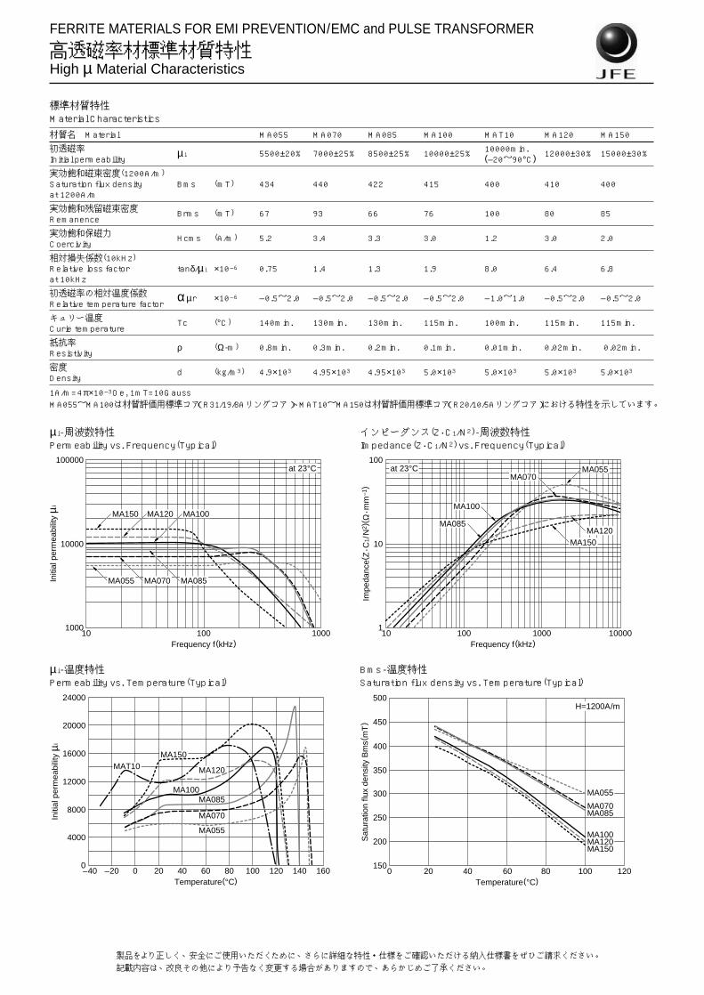
FERRITE MATERIALS FOR EMI PREVENTION/EMC and PULSE TRANSFORMER
高透磁率材標準材質特性High µ Material Characteristics
標準材質特性Material Characteristics
材質名 Material MA055 MA070 MA085 MA100 MAT10 MA120 MA150
初透磁率 µ i 5500±20% 7000±25% 8500±25% 10000±25% 10000min. 12000±30% 15000±30%Initial permeability (–20~90°C)
実効飽和磁束密度(1200A/m)Saturation flux density Bms (mT) 434 440 422 415 400 410 400at 1200A/m
実効飽和残留磁束密度 Brms (mT) 67 93 66 76 100 80 85Remanence
実効飽和保磁力 Hcms (A/m) 5.2 3.4 3.3 3.0 1.2 3.0 2.0Coercivity
相対損失係数(10kHz)Relative loss factor tanδ/µ i ×10–6 0.75 1.4 1.3 1.9 8.0 6.4 6.8at 10kHz
初透磁率の相対温度係数 α µr ×10–6 –0.5~2.0 –0.5~2.0 –0.5~2.0 –0.5~2.0 –1.0~1.0 –0.5~2.0 –0.5~2.0Relative temperature factor
キュリー温度 Tc (°C) 140min. 130min. 130min. 115min. 100min. 115min. 115min.Curie temperature
抵抗率 ρ (Ω-m) 0.8min. 0.3min. 0.2min. 0.1min. 0.01min. 0.02min. 0.02min.Resistivity
密度 d (kg/m3) 4.9×10³ 4.95×10³ 4.95×10³ 5.0×10³ 5.0×10³ 5.0×10³ 5.0×10³Density
1A/m=4π×10–3Oe, 1mT=10GaussMA055~MA100は材質評価用標準コア(R31/19/8Aリングコア)、MAT10~MA150は材質評価用標準コア(R20/10/5Aリングコア)における特性を示しています。
µ i-周波数特性 インピーダンス(Z・C1/N2)-周波数特性Permeability vs. Frequency(Typical) Impedance(Z・C1/N2) vs. Frequency(Typical)
10 100 1000Frequency f(kHz)
Initi
al p
erm
eabi
lity
µi
10000
100000
1000
at 23°C
MA150
MA055 MA070
MA120 MA100
MA085
10 100 100001000Frequency f(kHz)
Impe
danc
e(Z・C
1/N
2 )( Ω・m
m–1
)
10
100
1
at 23°C MA055
MA150
MA100
MA070
MA120MA085
µ i-温度特性 Bms-温度特性Permeability vs. Temperature(Typical) Saturation flux density vs. Temperature(Typical)
–40 0–20 20 40 60 80 100 120 140 160Temperature(°C)
Initi
al p
erm
eabi
lity
µi
20000
12000
16000
8000
4000
24000
0
MA150
MA120MAT10
MA100MA085
MA070
MA055
0 20 40 8060 100 120Temperature(°C)
Sat
urat
ion
flux
dens
ity B
ms(
mT
) 450
350
400
250
300
200
500
150
MA070MA085
MA100MA120MA150
MA055
H=1200A/m
26 製品をより正しく、安全にご使用いただくために、さらに詳細な特性・仕様をご確認いただける納入仕様書をぜひご請求ください。記載内容は、改良その他により予告なく変更する場合がありますので、あらかじめご了承ください。

FERRITE MATERIALS FOR EMI PREVENTION/EMC and PULSE TRANSFORMER
高透磁率材標準材質特性High µ Material Characteristics
MA055 直流ヒステリシス特性 MA100 直流ヒステリシス特性MA055 Static magnetization curves(Typical) MA100 Static magnetization curves(Typical)
–20 6040200 12010080Magnetic field H(A/m)
Flu
x de
nsity
B( m
T)
300
100
0
200
500
400
–100
23°C
100°C
–20 6040200 12010080Magnetic field H(A/m)
Flu
x de
nsity
B( m
T)
300
100
0
200
500
400
–100
23°C
100°C
MA070 直流ヒステリシス特性 MA120 直流ヒステリシス特性MA070 Static magnetization curves(Typical) MA120 Static magnetization curves(Typical)
–20 6040200 12010080Magnetic field H(A/m)
Flu
x de
nsity
B( m
T)
300
100
0
200
500
400
–100
23°C
100°C
–20 6040200 12010080Magnetic field H(A/m)
Flu
x de
nsity
B( m
T)
300
100
0
200
500
400
–100
23°C
100°C
MA085 直流ヒステリシス特性 MA150 直流ヒステリシス特性MA085 Static magnetization curves(Typical) MA150 Static magnetization curves(Typical)
–20 6040200 12010080Magnetic field H(A/m)
Flu
x de
nsity
B( m
T)
300
100
0
200
500
400
–100
23°C
100°C
–20 6040200 12010080Magnetic field H(A/m)
Flu
x de
nsity
B( m
T)
300
100
0
200
500
400
–100
23°C
100°C
27Specifications which provide more details for the proper and safe use of the described product are available upon request.All specifications are subject to change without notice.
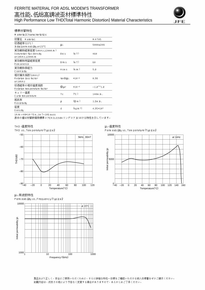
FERRITE MATERIAL FOR ADSL MODEM’S TRANSFORMER
高性能、低総高調波歪材標準特性High Performance Low THD(Total Harmonic Distortion) Material Characteristics
標準材質特性Material Characteristics
材質名 Material MAT05
初透磁率(23°C) µ i 5000±20%Initial permeability at 23°C
実効飽和磁束密度(10kHz,1200A/m)Saturation flux density Bms (mT) 460at 10kHz,1200A/m
実効飽和残留磁束密度 Brms (mT) 60Remanence
実効飽和保磁力 Hcms (A/m) 5.8Coercivity
相対損失係数(10kHz)Relative loss factor tanδ/µ i ×10–6 0.98at 10kHz
初透磁率の相対温度係数 α µr ×10–6 –1.0~1.0Relative temperature factor
キュリー温度 Tc (°C) 140min.Curie temperature
抵抗率 ρ (Ω-m) 1.5min.Resistivity
密度 d (kg/m3) 4.95×10³Density
1A/m=4π×10–3Oe, 1mT=10Gauss表中の値は材質評価用標準コア(R31/19/8Aリングコア)における特性を示しています。
THD-温度特性THD vs. Temperature(Typical)
µ i-温度特性Permeability vs. Temperature(Typical)
–40 –20 0 20 40 60 80 100 120Temperature(°C)
TH
D( d
B)
–50
–60
–70
–80
–90
5kHz, 30mT
–40 –20 16012080400 1401006020Temperature(°C)
Initi
al p
erm
eabi
lity
µi
10000
5000
0
at 1kHz
µ i-周波数特性Permeability vs. Frequency(Typical)
1 10 100 1000Frequency f(kHz)
Initi
al p
erm
eabi
lity
µi
10000
1000
at 23°C
28 製品をより正しく、安全にご使用いただくために、さらに詳細な特性・仕様をご確認いただける納入仕様書をぜひご請求ください。記載内容は、改良その他により予告なく変更する場合がありますので、あらかじめご了承ください。

6
FERRITE MATERIALS FOR POWER SUPPLY
高周波・低パワーロス材標準材質特性Low Power Loss for High Frequency Material Characteristics
標M
材
初I
実
S
実
R
実
C
パ
P
パ
P
キC
抵R
密D
1材
準材質特性aterial Characteristics
質名 Material MC2
透磁率 µi 23°C 1250nitial permeability
効飽和磁束密度(1200A/m)23°C 510
aturation flux density at 1200A/mBms (mT) 60°C 470
100°C 410
効飽和残留磁束密度23°C 180
emanenceBrms (mT) 60°C 130
100°C 110
効飽和保磁力23°C 40
oercivityHcms (A/m) 60°C 35
100°C 30
23°C 150
ワーロス(500kHz, 50mT)Pcv (kW/m3)
60°C 80
ower loss at 500kHz, 50mT 100°C 65
120°C 70
23°C 440
ワーロス(1MHz, 50mT)Pcv (kW/m3)
60°C 330
ower loss at 1MHz, 50mT 100°C 400
120°C 460
ュリー温度 Tc (°C) 260min.urie temperature
抗率 ρ (Ω-m) 15min.esistivity
度 d (kg/m3) 4.8×10³ensity
A/m=4π×10–3Oe, 1mT=10Gauss質評価コア(R-20/10/5Aリングコア)における代表特性を示しています。
MC2 µ i-周波数特性 MC2 µ i-温度特性MC2 Permeability vs. Frequency(Typical) MC2 Permeability vs. Temperature(Typical)
1 10 100 100001000Frequency f(kHz)
Initi
al p
erm
eabi
lity
µi
1000
100
10000
10
at 23°C
–40 0 40 80 120 160 200 240 280Temperature(°C)
Initi
al p
erm
eabi
lity
µi
1600
1200
800
400
2000
0
f=1kHz
製品をより正しく、安全にご使用いただくために、さらに詳細な特性・仕様をご確認いただける納入仕様書をぜひご請求ください。記載内容は、改良その他により予告なく変更する場合がありますので、あらかじめご了承ください。

FERRITE MATERIALS FOR POWER SUPPLY
高周波・低パワーロス材標準材質特性Low Power Loss for High Frequency Material Characteristics
MC2 パワーロス-温度特性 MC2 パワーロス-周波数特性MC2 Power loss vs. Temperature(Typical) MC2 Power loss vs. Frequency(Typical)
0 80604020 140120100Temperature(°C)
Pow
er lo
ss P
cv( k
W/m
3)
1000
100
10000
10
1MHz(50mT)
1MHz(100mT)
500kHz(100mT)
500kHz(50mT)
100 1000 10000Frequency f(kHz)
Pow
er lo
ss P
cv( k
W/m
3)
1000
100
10000
10
f •Bm=5.0×10⁴ T•Hz
f •Bm=2.5×10⁴ T•Hz
at 80°C
MC2 直流ヒステリシス特性 MC2 Bms-温度特性MC2 Static magnetization curves(Typical) MC2 Saturation flux density vs. Temperature(Typical)
–100 3002001000 600500400Magnetic field H(A/m)
Flu
x de
nsity
B( m
T)
300
100
0
200
500
400
–100
23°C
100°C
0 20 40 60 80 100 120 140Temperature(°C)
Sat
urat
ion
flux
dens
ity B
ms(
mT
)
600
0
100
200
300
400
500
H=1200A/m
MC2 パワーロス-磁束密度特性MC2 Power loss vs. Flux density(Typical)
10 100 1000Flux density Bm(mT)
Pow
er lo
ss P
cv( k
W/m
3) 1000
100
10
10000
1
500kHz
1MHz700kHzat 100°C
200kHz
7Specifications which provide more details for the proper and safe use of the described product are available upon request.All specifications are subject to change without notice.

FERRITE CORES FOR POWER SUPPLY
EEコアEE Cores
形状・寸法/特性Shapes and dimensions/Characteristics
形状 寸法 Dimensions(mm)Bobbin
Type A 2B B C D E min. 2F min. FEE-8.3 8.30+0.30, –0.20 8.00 4.00±0.10 3.60±0.20 1.80±0.20 6.10 5.80 3.00±0.10 EE-10.2 10.2+0.3, –0.2 11.0 5.50±0.15 4.70±0.20 2.40±0.20 7.60 8.10 4.20±0.15 EE-12.5 12.5±0.3 14.8 7.40±0.20 5.00±0.20 2.40±0.20 9.00 9.80 5.10±0.20EE-12.5T 12.5±0.3 8.9 4.45±0.20 5.00±0.20 2.40±0.20 9.00 4.70 2.55±0.20EE-13D 13.0±0.2 12.0 6.00±0.15 6.15±0.15 2.75±0.15 10.0 9.00 4.60±0.10 EE-14L 14.0±0.3 26.0 13.0±0.20 3.75±0.15 4.50±0.20 9.7 19.4 9.80±0.10EE-16A 16.0±0.3 14.4 7.20±0.20 4.80±0.20 4.00±0.20 11.7 10.0 5.20±0.20 EE-16B 16.0±0.3 24.4 12.2±0.2 4.80±0.20 4.00±0.20 11.7 20.0 10.2±0.2EE-16K 16.0±0.3 14.3 7.15±0.30 6.80±0.20 3.20+0.15, –0.20 12.5 10.8 5.50±0.10EE-16L 16.0±0.3 24.9 12.45±0.15 1.92±0.08 5.85±0.15 10.0 18.9 9.58±0.12EE-19A 19.0+0.4, –0.3 16.0 8.00±0.20 5.00±0.20 4.50±0.20 14.2 10.8 5.60±0.20 EE-19B 19.0+0.4, –0.3 26.8 13.4±0.3 5.00±0.20 4.50±0.20 14.2 21.4 11.0±0.3EE-19K 19.15±0.5 15.8 7.90±0.25 9.58±0.18 4.65±0.15 14.5 10.9 5.60±0.15EE-20K 20.0±0.3 27.1 13.55±0.25 5.00±0.20 4.55±0.15 14.3 22.0 11.15±0.15EE-20L 20.0±0.3 27.8 13.9±0.25 5.00±0.20 4.55±0.15 14.3 22.7 11.5±0.15EE-20N 20.0±0.4 19.9 9.95±0.20 5.65±0.25 5.70±0.20 14.1 14.0 7.20±0.20EE-22A 22.0+0.5, –0.4 18.8 9.40±0.20 5.80±0.30 5.80±0.30 15.6 10.4 5.40±0.20 EE-22B 22.0+0.5, –0.4 29.2 14.6±0.3 5.80±0.30 5.80±0.30 15.6 20.6 10.6±0.3 EE-22E 22.0±0.5 30.6 15.3±0.2 5.60±0.20 5.60±0.20 15.5 22.2 11.3±0.2EE-22K 22.0±0.3 29.3 14.65±0.25 5.75±0.25 5.75±0.25 16.0 21.2 10.8±0.2 EE-25S 25.0±0.5 20.3 10.15±0.15 6.40±0.20 6.40±0.25 18.6 13.2 6.75±0.15EE-25D 25.3±0.5 31.1 15.55±0.25 6.75±0.25 6.50±0.30 19.0 24.2 12.35±0.25EE-25K 25.4±0.5 18.9 9.46±0.19 6.29±0.19 6.35±0.25 18.6 12.4 6.41±0.19EE-25M 25.0+0.8, –0.7 25.1 12.55±0.25 7.20±0.30 7.25±0.25 17.5 17.4 8.95±0.25EE-25.4A 25.4+0.5, –0.4 19.0 9.50±0.20 6.35±0.30 6.35±0.30 18.6 12.4 6.40±0.20EE-25.4B 25.4+0.5, –0.4 32.0 16.0±0.3 6.35±0.30 6.35±0.30 18.6 25.2 12.9±0.3EE-27K 27.0±0.4 34.6 17.3±0.2 8.50±0.20 8.00±0.20 18.6 26.3 13.3±0.15EE-28S 28.0±0.4 21.0 10.5±0.2 10.7±0.25 7.20±0.25 18.6 12.0 6.20±0.20 EE-28R 28.0±0.5 25.5 12.75±0.15 10.6±0.2 7.20±0.30 18.4 16.3 8.25±0.10EE-28 28.0+0.6, –0.5 33.6 16.8±0.3 10.7±0.3 7.20±0.30 18.5 24.0 12.3±0.3EE-30A 30.0±0.5 26.4 13.2±0.3 10.7±0.3 10.7±0.3 19.5 15.8 8.20±0.30 EE-30L 30.0±0.5 30.0 15.0±0.2 7.10±0.20 6.90±0.30 19.5 19.4 9.95±0.25EE-30B 30.0+0.7, –0.5 42.6 21.3±0.3 10.7±0.3 10.7±0.3 19.5 32.0 16.3±0.3 EE-33A 33.0+0.6, –0.5 27.6 13.8±0.3 12.7±0.3 9.70±0.30 23.1 18.0 9.30±0.30EE-33K 33.0±0.7 28.3 14.15±0.2 12.7±0.3 9.70±0.30 23.5 18.9 9.65±0.20 EE-33B 33.0±0.5 46.6 23.3±0.3 12.7±0.3 9.70±0.30 23.1 37.6 19.1±0.3EE-34.3M 34.32±0.69 28.24 14.12±0.13 9.32±0.18 9.32±0.18 25.53 19.16 9.78±0.20EE-35K 35.0±0.5 30.2 15.1±0.2 11.75±0.3 10.0±0.3 24.5 17.8 9.10±0.20EE-35A 35.0+0.7, –0.5 31.0 15.5±0.3 10.0±0.3 10.0±0.3 24.5 18.4 9.50±0.30 EE-35B 35.0+0.7, –0.5 48.4 24.2±0.3 10.0±0.3 10.0±0.3 24.5 35.8 18.2±0.3EE-35C 35.0+0.7, –0.5 48.4 24.2±0.3 11.7±0.3 10.0±0.3 24.5 35.8 18.2±0.3EE-40E 40.0±0.6 33.5 16.75±0.3 11.65±0.35 11.65±0.35 26.8 20.7 10.65±0.3 EE-40A 40.0+0.7, –0.5 34.0 17.0±0.3 10.7±0.3 10.7±0.3 27.5 20.0 10.3±0.3EE-40S 40.0+0.7, –0.5 34.0 17.0±0.3 11.7±0.3 10.7±0.3 27.5 20.0 10.3±0.3EE-40B 40.0+0.9, –0.6 54.6 27.3±0.3 11.7±0.3 11.7±0.3 27.0 39.8 20.3±0.4 EE-40H 40.0+0.9, –0.6 55.3 27.65±0.3 11.7±0.3 11.7±0.3 27.0 40.4 20.6±0.4 EE-40.6M 40.64±0.81 32.96 16.48±0.13 12.45±0.25 12.45±0.25 28.5 20.68 10.54±0.2EE-42A 42.0+0.9, –0.7 42.0 21.0±0.3 15.0±0.4 12.0±0.3 29.5 29.6 15.1±0.3EE-42B 42.0+0.9, –0.7 42.0 21.0±0.3 19.6±0.4 12.0±0.3 29.5 29.6 15.1±0.3EE-44E 44.0±0.6 37.6 18.8±0.2 15.0±0.25 11.7±0.25 31.0 23.2 11.8±0.2 EE-44 44.0+0.9, –0.6 60.6 30.3±0.4 15.0±0.4 11.7±0.3 31.2 45.8 23.3±0.4EE-50A 50.0+1.0, –0.7 42.6 21.3±0.3 14.6±0.4 14.6±0.4 34.3 25.0 12.8±0.3 EE-50B 50.0±0.7 66.6 33.3±0.4 14.6±0.4 14.6±0.4 34.3 48.8 24.8±0.4EE-55 55.0+1.1, –0.8 55.0 27.5±0.4 20.7±0.4 17.0±0.4 37.2 37.0 18.9±0.4EE-60A 60.0+1.1, –0.8 44.6 22.3±0.3 15.6±0.4 15.6±0.4 43.7 27.4 14.0±0.3 EE-60B 60.0+1.2, –0.8 72.0 36.0±0.5 15.6±0.4 15.6±0.4 43.7 55.0 28.0±0.5EE-65K 65.0+1.5, –1.2 65.0 32.5±0.3 26.9±0.5 19.65±0.35 44.2 44.4 22.6±0.4EE-70K 70.0±0.8 77.7 38.85±0.35 15.6±0.4 15.6±0.4 54.1 61.0 30.85±0.35EE-80K 79.3±1.6 75.0 37.5±0.5 19.8±0.4 19.75±0.25 59.4 56.0 28.3±0.3
A
2B
B
F
2F
ED
C
8 製品をより正しく、安全にご使用いただくために、さらに詳細な特性・仕様をご確認いただける納入仕様書をぜひご請求ください。記載内容は、改良その他により予告なく変更する場合がありますので、あらかじめご了承ください。

FERRITE CORES FOR POWER SUPPLY
EEコアEE Cores
形状 AL value(nH/N2)±25% コア定数 Core parameters Weight
Type MB1 MB3 MB4 MBT1 C1(mm–1) Le(mm) Ae(mm2) Amin(mm2) Ve(mm3) (g/set)EE-8.3 649 750 750 927 2.82 19.5 6.92 6.48 135 0.7EE-10.2 825 950 950 1190 2.27 26.1 11.5 11.3 301 1.5EE-12.5 910 1100 1100 1330 2.10 31.4 14.9 12.0 469 2.8EE-12.5T 1250 1500 1500 1760 1.42 21.6 15.2 12.0 328 1.9EE-13D 1060 1200 1200 1530 1.77 30.2 17.1 16.9 517 2.6EE-14L 620 730 730 900 3.12 52.1 16.7 15.0 870 4.7EE-16A 1050 1300 1300 1540 1.83 35.1 19.2 19.2 674 3.5EE-16B 734 900 900 1120 2.87 55.1 19.2 19.2 1060 5.3EE-16K 1080 1260 1260 1530 1.67 36.7 21.9 21.6 805 4.1EE-16L 462 500 500 713 4.64 51.8 11.2 11.0 577 3.0EE-19A 1140 1400 1400 1670 1.73 39.7 23.0 22.5 912 4.7EE-19B 791 900 900 1210 2.69 61.3 22.8 22.5 1400 7.1EE-19K 2280 2300 2300 3020 0.911 39.6 43.5 42.1 1730 8.9EE-20K 790 940 940 1180 2.52 61.8 24.5 22.8 1520 7.8EE-20L 795 950 950 1200 2.58 63.2 24.5 22.8 1550 8.0EE-20N 1360 1500 1500 2020 1.46 46.2 31.7 31.1 1460 7.6EE-22A 1730 1900 1900 2530 1.12 42.1 37.5 33.6 1580 8.6EE-22B 1210 1500 1500 1850 1.73 62.8 36.3 33.6 2280 12.1EE-22E 1070 1300 1300 1600 1.89 65.5 34.6 31.4 2260 12.1EE-22K 1150 1400 1400 1750 1.84 63.6 34.6 32.2 2200 11.7EE-25S 1630 1870 1870 2430 1.22 49.7 40.6 37.8 2020 10.5EE-25D 1210 1500 1500 1820 1.70 72.0 42.3 40.5 3050 15.6EE-25K 1610 2000 2000 2400 1.23 48.2 39.1 38.4 1880 9.7EE-25M 1760 2090 2090 2600 1.12 57.7 51.7 51.1 2990 15.4EE-25.4A 1650 1850 1850 2450 1.20 48.1 40.1 39.4 1930 10.0EE-25.4B 1160 1500 1500 1790 1.84 74.1 40.2 39.4 2980 15.1EE-27K 1840 2220 2220 2800 1.13 76.8 68.0 68.0 5220 26.7EE-28S 3450 4080 4080 5060 0.565 49.3 87.3 77.0 4310 23.2EE-28R 3040 3800 3800 4540 0.661 57.6 87.2 76.3 5020 27.0EE-28 2490 3200 3200 3800 0.844 73.6 87.2 77.0 6420 34.1EE-30A 3780 4410 4410 5630 0.530 58.0 109 107 6350 33.5EE-30L 1910 2210 2210 2900 1.09 65.3 60.1 49.0 3930 22.3EE-30B 2630 3170 3170 4070 0.823 90.4 110 107 9930 51.1EE-33A 3660 4400 4400 5470 0.552 65.6 119 114 7800 40.6EE-33K 3590 4300 4300 5410 0.574 67.2 117 114 7870 40.9EE-33B 2490 3000 3000 3890 0.884 104 118 107 12300 62.7EE-34.3M 2390 2860 2860 3600 0.854 69.4 81.3 77.2 5640 29.3EE-35K 3750 4400 4400 5670 0.550 68.3 124 118 8490 45.1EE-35A 3140 4000 4000 4760 0.662 69.9 106 100 7380 39.2EE-35B 2180 2700 2700 3420 1.01 105 104 100 10800 56.3EE-35C 2550 3200 3200 3990 0.863 105 121 117 12700 65.8EE-40E 3870 4500 4500 5900 0.544 77.2 142 136 11000 57.6EE-40A 3470 3960 3960 5290 0.608 77.4 127 114 9860 52.6EE-40S 3750 4800 4800 5690 0.556 77.4 139 125 10700 57.5EE-40B 2760 3500 3500 4340 0.808 117 145 137 17000 88.2EE-40H 2730 3190 3190 4300 0.816 118 145 137 17200 89.3EE-40.6M 4000 4790 4790 6070 0.521 77.5 149 144 11500 60.3EE-42A 4000 5200 5200 6210 0.542 97.1 179 177 17400 89.7EE-42B 5220 6500 6500 8080 0.415 97.1 234 231 22700 117EE-44E 4660 5600 5600 7170 0.458 87.1 190 176 16600 87.4EE-44 3130 4000 4000 4950 0.721 133 185 176 24600 127EE-50A 5070 6400 6400 7850 0.427 96.3 226 213 21700 115EE-50B 3490 4400 4400 5560 0.649 144 222 213 32000 166EE-55 6360 8000 8000 0.350 123 353 352 43600 226EE-60A 4960 6500 6500 0.443 110 248 242 27300 143EE-60B 3390 4300 4300 0.678 166 244 242 40500 207EE-65K 10000 10000 0.276 147 533 529 78300 406EE-70K 3670 3670 0.774 187 242 236 45300 230EE-80K 5750 5750 0.492 184 373 364 68500 351
9Specifications which provide more details for the proper and safe use of the described product are available upon request.All specifications are subject to change without notice.

FERRITE CORES FOR POWER SUPPLY
EIコアEI Cores
形状・寸法/特性Shapes and dimensions/Characteristics
形状 寸法 Dimensions(mm)Bobbin
Type A B+I B C D E min. F I
EI-12.5 12.5±0.3 8.90±0.35 7.40±0.20 5.00±0.20 2.40±0.20 9.0 5.10±0.20 1.50±0.15 EI-12.5K 12.5±0.3 9.40±0.40 7.40±0.20 5.00±0.20 2.40±0.20 9.0 5.10±0.20 2.00±0.20EI-16 16.0±0.3 14.2±0.4 12.2±0.2 4.80±0.20 4.00±0.20 11.7 10.2±0.2 2.00±0.20 EI-19 19.0+0.4, –0.3 15.8±0.5 13.4±0.3 5.00±0.20 4.50±0.20 14.2 11.0±0.3 2.40±0.20 EI-20K 20.0±0.3 15.85±0.35 13.55±0.25 5.00±0.20 4.55±0.15 14.3 11.15±0.15 2.30±0.10 EI-22 22.0+0.5, –0.4 18.6±0.5 14.6±0.3 5.80±0.30 5.80±0.30 15.6 10.6±0.3 4.00±0.20 EI-22D 22.0+0.5, –0.4 19.1±0.5 14.6±0.3 5.75±0.30 5.80±0.30 15.6 10.6±0.3 4.50±0.20 EI-22E 22.0±0.5 19.3±0.4 15.3±0.2 5.60±0.20 5.60±0.20 15.5 11.3±0.2 4.00±0.20EI-25L 25.0±0.5 20.0±0.4 16.9±0.3 6.40±0.20 6.40±0.20 18.4 13.5±0.3 3.10±0.10EI-25D 25.3±0.5 18.25±0.45 15.55±0.25 6.75±0.25 6.50±0.30 19.0 12.35±0.25 2.70±0.20 EI-25.4 25.4+0.5, –0.4 19.2±0.5 16.0±0.3 6.35±0.30 6.35±0.30 18.6 12.9±0.3 3.20±0.20EI-25.4K 25.4+0.5, –0.4 12.7±0.4 9.50±0.20 6.35±0.30 6.35±0.30 18.6 6.40±0.20 3.20±0.20EI-28 28.0+0.6, –0.5 20.3±0.6 16.8±0.3 10.7±0.3 7.20±0.30 18.5 12.3±0.3 3.50±0.30 EI-30 30.0+0.7, –0.5 26.8±0.6 21.3±0.3 10.7±0.3 10.7±0.3 19.5 16.3±0.3 5.50±0.30 EI-33 33.0±0.5 28.3±0.6 23.3±0.3 12.7±0.3 9.70±0.30 23.1 19.1±0.3 5.00±0.30 EI-33E 33.0±0.5 28.75±0.55 23.75±0.25 12.7±0.3 9.70±0.30 23.6 19.25±0.25 5.00±0.30 EI-35A 35.0+0.7, –0.5 29.2±0.6 24.2±0.3 10.0±0.3 10.0±0.3 24.5 18.2±0.3 5.00±0.30 EI-35E 35.0+0.7, –0.5 29.7±0.5 24.2±0.3 11.7±0.3 10.0±0.3 24.6 18.25±0.25 5.50±0.20EI-40 40.0+0.9, –0.6 34.8±0.6 27.3±0.3 11.7±0.3 11.7±0.3 27.0 20.3±0.4 7.50±0.30 EI-44 44.0+0.9, –0.6 37.3±0.7 30.3±0.4 15.0±0.4 11.7±0.3 31.2 23.3±0.4 7.00±0.30 EI-50 50.0±0.7 42.3±0.7 33.3±0.4 14.6±0.4 14.6±0.4 34.3 24.8±0.4 9.00±0.30 EI-60 60.0+1.2, –0.8 44.5±0.8 36.0±0.5 15.6±0.4 15.6±0.4 43.7 28.0±0.5 8.50±0.30
形状 AL value(nH/N2)±25% コア定数 Core parameters Weight
Type MB1 MB3 MB4 MBT1 C1(mm–1) Le(mm) Ae(mm2) Amin(mm2) Ve(mm3) (g/set)
EI-12.5 1260 1500 1500 1780 1.44 21.4 14.9 12.0 319 1.9EI-12.5K 1260 1500 1500 1780 1.44 21.4 14.9 12.0 319 1.9EI-16 1100 1300 1300 1630 1.81 34.7 19.2 19.2 666 3.4EI-19 1180 1200 1200 1760 1.71 39.3 23.0 22.5 903 4.7EI-20K 1230 1400 1400 1840 1.63 39.6 24.3 22.8 963 5.0EI-22 1790 2000 2000 2660 1.11 41.7 37.5 33.6 1560 8.6EI-22D 1800 1970 1970 2670 1.11 41.8 37.7 33.4 1580 8.8EI-22E 1530 1730 1730 2180 1.20 43.0 35.8 31.4 1540 8.5EI-25L 1690 1700 1700 2540 1.21 49.4 40.7 39.7 2010 10.4EI-25D 1770 2200 2200 2660 1.14 46.9 41.0 36.5 1920 10.0EI-25.4 1700 2100 2100 2560 1.20 48.4 40.3 39.4 1950 10.1EI-25.4K 1970 2560 2560 2750 0.880 35.4 40.2 39.4 1420 7.5EI-28 3460 3940 3940 5130 0.574 48.5 84.4 75.0 4090 22.2EI-30 3900 4500 4500 5860 0.524 58.2 111 107 6460 34.2EI-33 3740 4400 4400 5690 0.559 66.7 119 107 7950 41.6EI-33E 3690 4500 4500 5620 0.567 67.5 119 114 8030 41.9EI-35A 3190 3830 3830 4870 0.659 67.7 103 100 6950 36.7EI-35E 3750 4500 4500 5720 0.558 68.1 122 117 8310 43.9EI-40 4120 5000 5000 6330 0.516 76.9 149 137 11500 61.3EI-44 4690 6000 6000 7250 0.461 86.7 188 176 16300 86.2EI-50 5220 6500 6500 8130 0.417 94.9 228 213 21600 115EI-60 5000 6500 6500 0.444 110 248 242 27200 142
A
B+I
B
F
IED
C
10 製品をより正しく、安全にご使用いただくために、さらに詳細な特性・仕様をご確認いただける納入仕様書をぜひご請求ください。記載内容は、改良その他により予告なく変更する場合がありますので、あらかじめご了承ください。

FERRITE CORES FOR POWER SUPPLY
EE/EIコア用ボビンBobbins for EE and EI Cores
形状・寸法Shapes and dimensions
形状寸法 Dimension(mm) No. of コア方向*2 適合コア
Type A B C*1 D*1 E*1 F*1 G H J P1 P2 P0 ød L terminal Core Applied core
max. max. min. min. max. max. max. min. min. pins direction EE core EI core
BE8.3KP6 8.1 7.7 4.05 2.05 5.7 5.7 8.1 1.3 4.6 2.5 2.5 6.0 0.4 3.7 3-3 V EE8.3
BE10.2KP8 10.3 9.1 5.15 2.65 7.3 8.0 10.3 1.8 6.6 2.5 2.5 8.0 0.49 3.7 4-4 V EE10.2
BE12.5LP10 12.5 8.3 5.3 2.7 8.6 4.8 12.5 2.3 3.3 2.5 2.5 7.5 0.49 4.0 5-5 V EI12.5
BE13KP10 12.2 10.4 6.4 3.0 10.0 8.9 12.7 2.9 7.3 2.5 2.5 8.5 0.49 3.7 5-5 V EE13D
BE16AP10 16.2 13.9 5.0 4.25 11.6 9.9 13.2 2.9 8.0 3.3 3.3 10.5 0.6 5.5 5-5 V EE16A EI16
BE19NP8 19.1 16.5 5.4 4.9 14.1 10.7 15.1 3.4 8.4 5.0 5.0 10.0 0.6 4.0 4-4 V EE19A EI19, 20K
BE22KP8 22.2 16.4 6.1 6.1 15.2 10.3 17.2 3.6 8.4 5.0 5.0 12.5 0.8 6.0 4-4 V EE22A EI22, D
BE22NP8 22.2 27.7 6.2 6.2 15.3 20.6 17.2 3.3 18.3 5.0 5.0 12.5 0.8 4.0 4-4 V EE22B, K
BE25NP8 25.0 19.3 7.3 7.1 17.6 11.9 17.7 4.1 9.6 5.0 5.0 12.5 0.8 3.5 4-4 V EI25D
BE25PP11 26.5 16.9 7.2 7.1 18.0 11.9 19.2 4.5 9.9 4.5 5.5 15.6 0.8 6.0 6-5 V EI25D
BE28AP12 28.5 19.3 11.2 7.7 18.6 11.8 23.8 4.4 9.8 5.0 5.0 18.0 0.8 3.8 6-6 V EE28S EI28
BE28PP10 26.0 20.6 11.4 7.8 18.2 11.8 22.0 4.1 9.8 5.0 5.0 17.5 0.8 3.5 5-5 V EE28S EI28
BE30KP12 30.2 24.7 11.3 11.1 19.8 15.8 26.2 3.0 13.4 5.0 5.0 20.0 0.8 5.0 6-6 V EE30A EI30
BE30NP10 30.2 24.7 11.3 11.2 19.2 15.6 25.0 2.7 13.6 5.0 5.0 20.0 0.8 7.0 5-5 V EE30A EI30
BE30AP12 30.2 47.7 11.1 11.1 19.5 32.0 26.6 3.1 13.0 5.0 40.0 0.8 5.5 6-6 H EE30B
BE33KP10 26.2 23.0 13.2 10.2 22.8 18.3 28.2 5.3 16.3 5.0 5.0 22.5 0.8 7.5 5-5 V EE33K EI33, E
BE33MP12 33.2 28.8 13.3 10.3 23.2 18.7 28.2 5.3 16.5 5.0 5.0 22.5 0.8 7.0 6-6 V EE33K EI33E
BE35LP10 32.2 26.7 10.5 10.5 23.9 17.8 25.7 5.5 15.0 5.0 5.0 20.0 0.8 7.0 5-5 V EE35A EI35A
BE35NP12 30.2 24.7 10.5 10.5 24.2 17.5 25.2 5.6 15.3 5.0 5.0 20.0 0.8 7.0 6-6 V EE35A EI35A
BE40KP12 32.1 32.5 12.2 12.2 27.2 19.9 28.2 6.3 17.6 5.0 5.0 22.5 0.8 5.0 6-6 V EE40A EI40
BE40MP12 32.1 32.5 12.2 12.2 27.2 19.9 28.2 6.3 17.6 5.0 5.0 25.0 0.8 5.0 6-6 V EE40A EI40
BE40NP12 36.0 30.7 12.2 12.2 26.5 19.7 30.2 6.6 17.2 5.0 5.0 25.0 0.8 7.0 6-6 V EE40E EI40
BE40AP12 36.2 59.2 12.0 12.0 27.0 40.6 31.5 6.3 37.8 6.0 50.0 1.0 5.5 6-6 H EE40H
BE40BP7 40.0 59.2 12.1 12.1 27.0 39.8 31.4 6.0 37.0 6.0 50.0 1.0 4.1 7-7 H EE40B
BE44LP16 40.0 34.0 15.3 12.4 30.6 22.8 34.0 8.0 19.9 5.0 5.0 27.5 1.0 4.5 8-8 V EE44E EI44
BE50MP12 50.2 36.8 15.2 15.2 33.3 24.1 36.3 7.9 21.1 7.5 7.5 27.5 1.0 9.0 6-6 V EE50A EI50
BE60LP12 56.2 38.8 16.5 16.5 43.5 27.2 45.2 12.2 23.7 7.5 7.5 35.0 1.0 5.0 6-6 V EE60A EI60*1コア勘合面 *2V=縦使用 Vertical use、H=横使用 Horizontal use
E
D H
JL
GP0C
B
FA
P1 P1P1
P2 P2P2
ød
縦使用 Vertical use(V)
L
A
G
C
F
J
E
D H
B
P0
P1
P1
P1
P1
P1
ød
横使用 Horizontal use(H)
11Specifications which provide more details for the proper and safe use of the described product are available upon request.All specifications are subject to change without notice.
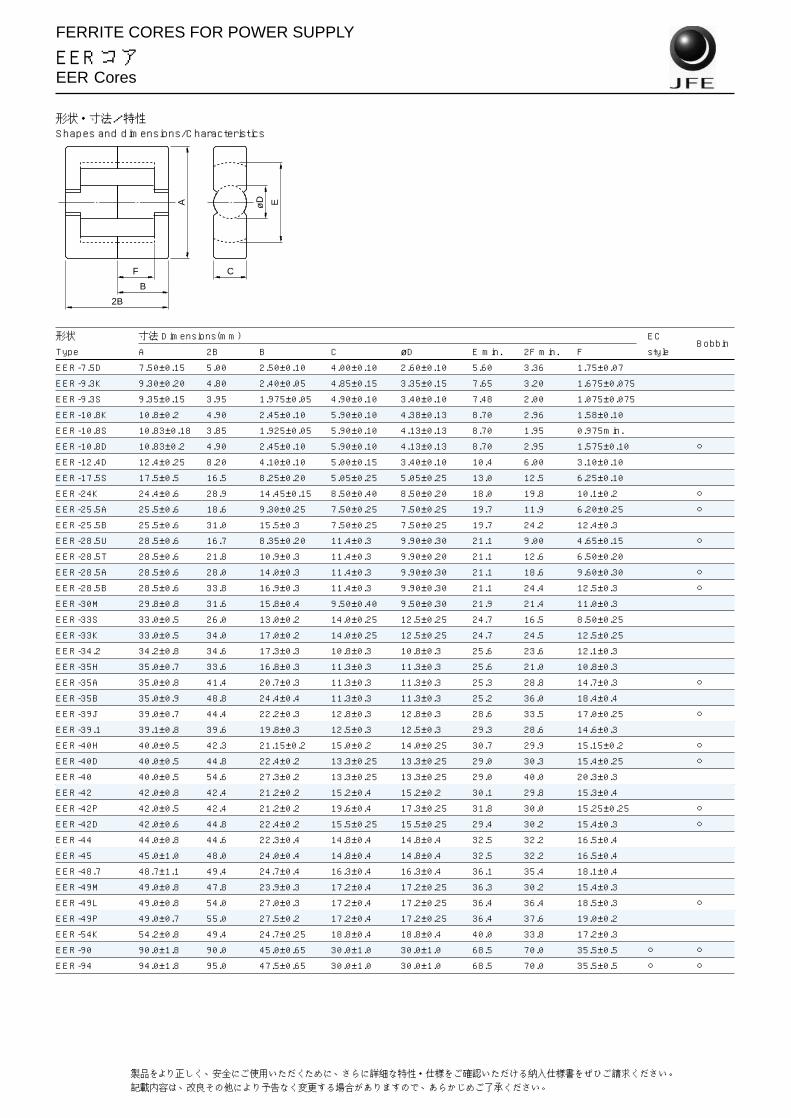
FERRITE CORES FOR POWER SUPPLY
EERコアEER Cores
形状・寸法/特性Shapes and dimensions/Characteristics
形状 寸法 Dimensions(mm) ECBobbin
Type A 2B B C øD E min. 2F min. F style
EER-7.5D 7.50±0.15 5.00 2.50±0.10 4.00±0.10 2.60±0.10 5.60 3.36 1.75±0.07EER-9.3K 9.30±0.20 4.80 2.40±0.05 4.85±0.15 3.35±0.15 7.65 3.20 1.675±0.075EER-9.3S 9.35±0.15 3.95 1.975±0.05 4.90±0.10 3.40±0.10 7.48 2.00 1.075±0.075EER-10.8K 10.8±0.2 4.90 2.45±0.10 5.90±0.10 4.38±0.13 8.70 2.96 1.58±0.10EER-10.8S 10.83±0.18 3.85 1.925±0.05 5.90±0.10 4.13±0.13 8.70 1.95 0.975min.
EER-10.8D 10.83±0.2 4.90 2.45±0.10 5.90±0.10 4.13±0.13 8.70 2.95 1.575±0.10
EER-12.4D 12.4±0.25 8.20 4.10±0.10 5.00±0.15 3.40±0.10 10.4 6.00 3.10±0.10EER-17.5S 17.5±0.5 16.5 8.25±0.20 5.05±0.25 5.05±0.25 13.0 12.5 6.25±0.10EER-24K 24.4±0.6 28.9 14.45±0.15 8.50±0.40 8.50±0.20 18.0 19.8 10.1±0.2
EER-25.5A 25.5±0.6 18.6 9.30±0.25 7.50±0.25 7.50±0.25 19.7 11.9 6.20±0.25
EER-25.5B 25.5±0.6 31.0 15.5±0.3 7.50±0.25 7.50±0.25 19.7 24.2 12.4±0.3EER-28.5U 28.5±0.6 16.7 8.35±0.20 11.4±0.3 9.90±0.30 21.1 9.00 4.65±0.15
EER-28.5T 28.5±0.6 21.8 10.9±0.3 11.4±0.3 9.90±0.20 21.1 12.6 6.50±0.20EER-28.5A 28.5±0.6 28.0 14.0±0.3 11.4±0.3 9.90±0.30 21.1 18.6 9.60±0.30
EER-28.5B 28.5±0.6 33.8 16.9±0.3 11.4±0.3 9.90±0.30 21.1 24.4 12.5±0.3
EER-30M 29.8±0.8 31.6 15.8±0.4 9.50±0.40 9.50±0.30 21.9 21.4 11.0±0.3EER-33S 33.0±0.5 26.0 13.0±0.2 14.0±0.25 12.5±0.25 24.7 16.5 8.50±0.25EER-33K 33.0±0.5 34.0 17.0±0.2 14.0±0.25 12.5±0.25 24.7 24.5 12.5±0.25EER-34.2 34.2±0.8 34.6 17.3±0.3 10.8±0.3 10.8±0.3 25.6 23.6 12.1±0.3EER-35H 35.0±0.7 33.6 16.8±0.3 11.3±0.3 11.3±0.3 25.6 21.0 10.8±0.3EER-35A 35.0±0.8 41.4 20.7±0.3 11.3±0.3 11.3±0.3 25.3 28.8 14.7±0.3
EER-35B 35.0±0.9 48.8 24.4±0.4 11.3±0.3 11.3±0.3 25.2 36.0 18.4±0.4EER-39J 39.0±0.7 44.4 22.2±0.3 12.8±0.3 12.8±0.3 28.6 33.5 17.0±0.25
EER-39.1 39.1±0.8 39.6 19.8±0.3 12.5±0.3 12.5±0.3 29.3 28.6 14.6±0.3EER-40H 40.0±0.5 42.3 21.15±0.2 15.0±0.2 14.0±0.25 30.7 29.9 15.15±0.2
EER-40D 40.0±0.5 44.8 22.4±0.2 13.3±0.25 13.3±0.25 29.0 30.3 15.4±0.25
EER-40 40.0±0.5 54.6 27.3±0.2 13.3±0.25 13.3±0.25 29.0 40.0 20.3±0.3EER-42 42.0±0.8 42.4 21.2±0.2 15.2±0.4 15.2±0.2 30.1 29.8 15.3±0.4EER-42P 42.0±0.5 42.4 21.2±0.2 19.6±0.4 17.3±0.25 31.8 30.0 15.25±0.25
EER-42D 42.0±0.6 44.8 22.4±0.2 15.5±0.25 15.5±0.25 29.4 30.2 15.4±0.3
EER-44 44.0±0.8 44.6 22.3±0.4 14.8±0.4 14.8±0.4 32.5 32.2 16.5±0.4EER-45 45.0±1.0 48.0 24.0±0.4 14.8±0.4 14.8±0.4 32.5 32.2 16.5±0.4EER-48.7 48.7±1.1 49.4 24.7±0.4 16.3±0.4 16.3±0.4 36.1 35.4 18.1±0.4EER-49M 49.0±0.8 47.8 23.9±0.3 17.2±0.4 17.2±0.25 36.3 30.2 15.4±0.3EER-49L 49.0±0.8 54.0 27.0±0.3 17.2±0.4 17.2±0.25 36.4 36.4 18.5±0.3
EER-49P 49.0±0.7 55.0 27.5±0.2 17.2±0.4 17.2±0.25 36.4 37.6 19.0±0.2EER-54K 54.2±0.8 49.4 24.7±0.25 18.8±0.4 18.8±0.4 40.0 33.8 17.2±0.3EER-90 90.0±1.8 90.0 45.0±0.65 30.0±1.0 30.0±1.0 68.5 70.0 35.5±0.5
EER-94 94.0±1.8 95.0 47.5±0.65 30.0±1.0 30.0±1.0 68.5 70.0 35.5±0.5
2B
B
F
A EøD
C
12 製品をより正しく、安全にご使用いただくために、さらに詳細な特性・仕様をご確認いただける納入仕様書をぜひご請求ください。記載内容は、改良その他により予告なく変更する場合がありますので、あらかじめご了承ください。

FERRITE CORES FOR POWER SUPPLY
EERコアEER Cores
形状 AL value(nH/N2)±25% コア定数 Core parameters Weight
Type MB1 MB3 MB4 MBT1 C1(mm–1) Le(mm) Ae(mm2) Amin(mm2) Ve(mm3) (g/set)
EER-7.5D 735 839 839 985 2.10 12.5 5.96 5.31 74.7 0.45
EER-9.3K 840 955 955 1110 1.74 14.0 8.04 8.81 113 0.69
EER-9.3S 1080 1210 1210 1390 1.27 11.9 9.31 9.07 111 0.66
EER-10.8K 1290 1460 1460 1700 1.15 14.3 12.3 15.1 176 1.1
EER-10.8S 1340 1510 1510 1740 1.04 12.4 12.0 10.2 149 0.90
EER-10.8D 1220 1380 1380 1610 1.21 14.4 12.0 10.2 173 0.98
EER-12.4D 705 700 700 996 2.53 23.4 9.27 8.88 217 1.2
EER-17.5S 940 1100 1100 1350 1.94 40.1 20.7 20.0 830 4.38
EER-24K 1920 2260 2260 2890 1.07 62.5 58.5 53.7 3660 19.8
EER-25.5A 1810 2000 2000 2670 1.08 47.6 44.2 42.4 2100 11.0
EER-25.5B 1280 1500 1500 1960 1.65 72.4 43.8 42.4 3170 16.3
EER-28.5U 3580 4170 4170 5160 0.524 42.9 81.9 77.0 3510 19.2
EER-28.5T 3300 3890 3890 4810 0.579 50.8 87.7 77.0 4450 25.5
EER-28.5A 2740 3270 3270 4120 0.744 63.4 85.2 77.0 5400 29.3
EER-28.5B 2370 2850 2850 3620 0.887 74.9 84.5 77.0 6340 34.0
EER-30M 2220 2650 2650 3340 0.925 70.7 76.4 70.9 5400 28.9
EER-33S 3990 4800 4800 5970 0.506 62.0 123 121 7610 40.6
EER-33K 3300 4200 4200 5040 0.637 78.0 122 121 9560 50.1
EER-34.2 2580 3200 3200 3950 0.820 79.2 96.6 91.6 7660 40.4
EER-35H 3090 3700 3700 4700 0.678 75.1 111 100 8310 45.1
EER-35A 2620 3300 3300 4050 0.822 90.4 110 100 9940 53.4
EER-35B 2280 2800 2800 3570 0.963 105 109 100 11500 60.9
EER-39J 2850 3500 3500 4440 0.766 102 133 129 13500 69.8
EER-39.1 2880 3480 3480 4470 0.749 92.9 124 123 11500 59.9
EER-40H 3530 4000 4000 5470 0.613 96.1 157 147 15000 79.9
EER-40D 3400 4300 4300 5280 0.638 97.5 153 139 14900 80.3
EER-40 2870 3490 3490 4520 0.773 117 151 139 17700 94.3
EER-42 4080 5200 5200 6320 0.531 96.6 182 178 17600 91.9
EER-42P 5150 6300 6300 7960 0.419 96.0 229 222 22000 116
EER-42D 4450 5200 5200 6890 0.487 97.8 201 189 19600 104
EER-44 3810 4400 4400 5930 0.573 103 179 169 18400 96.8
EER-45 3930 4760 4760 6130 0.558 106 190 172 20100 108
EER-48.7 4330 5260 5260 6780 0.509 113 221 209 24900 132
EER-49M 5090 6500 6500 7920 0.429 105 245 230 25900 140
EER-49L 4500 5570 5570 7070 0.493 119 241 225 28500 153
EER-49P 4430 5380 5380 6970 0.501 121 240 225 29000 155
EER-54K 5350 6000 6000 0.412 115 280 278 32200 169
EER-90 6720 8250 8250 0.347 215 619 559 133000 698
EER-94 7490 9210 9210 0.312 222 712 707 158000 819
13Specifications which provide more details for the proper and safe use of the described product are available upon request.All specifications are subject to change without notice.

FERRITE CORES FOR POWER SUPPLY
EIRコアEIR Cores
形状・寸法/特性Shapes and dimensions/Characteristics
形状 寸法 Dimensions(mm)Bobbin
Type A B+I B C øD E min. F I
EIR-12.4D 12.4±0.25 5.00±0.20 4.10±0.10 5.00±0.15 3.40±0.10 10.4 3.10±0.10 0.90±0.10EIR-25.5 25.5±0.6 18.6±0.5 15.5±0.3 7.50±0.25 7.50±0.25 19.7 12.4±0.3 3.10±0.20
EIR-28.5P 28.5±0.6 16.7±0.4 13.7±0.2 11.4±0.25 9.90±0.25 21.0 9.30±0.30 3.00±0.20
EIR-28.5N 28.5±0.6 17.6±0.4 14.6±0.2 11.4±0.3 9.90±0.30 21.1 10.2±0.2 3.00±0.20EIR-28.5 28.5±0.6 21.3±0.5 16.9±0.3 11.4±0.3 9.90±0.30 21.1 12.5±0.3 4.40±0.20EIR-30K 30.0±0.5 26.5±0.5 21.5±0.2 12.0±0.2 12.0±0.2 20.2 16.5±0.2 5.00±0.30EIR-35 35.0±0.9 29.4±0.55 24.4±0.3 11.3±0.3 11.3±0.25 25.2 18.4±0.4 5.00±0.25EIR-40 40.0±0.8 34.3±0.7 27.3±0.4 13.3±0.3 13.3±0.3 27.25 20.3±0.4 7.00±0.30EIR-90 90.0±1.8 55.0±0.95 45.0±0.65 30.0±1.0 30.0±1.0 68.5 35.5±0.5 10.0±0.3EIR-94 94.0±1.8 59.5±0.95 47.5±0.65 30.0±1.0 30.0±1.0 68.5 35.5±0.5 12.0±0.3
形状 AL value(nH/N2)±25% コア定数 Core parameters Weight
Type MB1 MB3 MB4 MBT1 C1(mm–1) Le(mm) Ae(mm2) Amin(mm2) Ve(mm3) (g/set)
EIR-12.4D 929 800 800 1290 1.85 17.1 9.21 8.88 157 0.85
EIR-25.5 1850 2200 2200 2750 1.08 47.6 44.3 42.4 2110 11.1
EIR-28.5P 3610 4170 4170 5240 0.526 42.4 80.6 68.4 3420 19.2
EIR-28.5N 3500 4300 4300 5100 0.548 44.2 80.6 68.4 3560 19.9
EIR-28.5 3410 4300 4300 5030 0.578 50.0 86.6 77.0 4330 24.0
EIR-30K 4140 4930 4930 6180 0.486 57.8 119 113 6880 37.0
EIR-35 3350 4010 4010 5070 0.621 67.9 109 100 7430 40.2
EIR-40 4280 5140 5140 6530 0.492 76.6 156 139 11900 65.4
EIR-90 9560 11700 11700 0.237 145 614 544 89100 486
EIR-94 10700 13100 13100 0.212 151 713 707 108000 582
B+I
B I
F
A EøD
C
15Specifications which provide more details for the proper and safe use of the described product are available upon request.All specifications are subject to change without notice.

FERRITE CORES FOR POWER SUPPLY
EER/EIRコア用ボビンBobbins for EER and EIR Cores
形状・寸法Shapes and dimensions
品名 寸法 Dimension(mm) No. of コア方向*2 適合コア
Part A B C*1 øD*1 E*1 F*1 G H J P1 P0 ød L terminal Core Applied core
No. max. max. min. min. max. max. max. min. min. pins direction EER core EIR core
BER10.8LD10 11 5.05 6.1 4.4 8.6 2.95 12.6 1.5 2.1 2.0 11 0.7 1.4 5-5 SMD EER10.8K
BER24AP12 29.0 35.3 9.0 8.8 17.6 19.7 21.0 3.4 17.6 5.0 25.0 0.8 3.9 6-6 H EER24K
BER25.5KP8 22.0 18.0 7.9 7.9 19.5 11.9 19.6 4.5 9.8 5.0 12.5 0.8 5.0 4-4 V EER25.5A EIR25.5
BER28.5KP10 25.0 26.5 11.8 10.3 20.9 18.5 23.0 4.1 16.2 5.0 17.5 0.8 5.0 5-5 V EER28.5A
BER28.5SP12 31.0 26.4 11.8 10.3 21.0 18.4 26.0 4.3 16.6 5.0 17.5 0.8 3.6 6-6 V EER28.5A
BER28.5TP12 31.0 26.4 11.8 10.3 21.0 18.4 26.0 4.3 16.6 5.0 22.0 0.8 3.6 6-6 V EER28.5A
BER28.5LP10 25.0 32.3 11.8 10.2 20.9 24.3 23.0 4.1 22.0 5.0 17.5 0.8 5.0 5-5 V EER28.5B
BER28.5MP12 28.5 33.2 11.8 10.3 21.1 24.3 26.0 4.3 22.2 5.0 17.5 1.0 3.6 6-6 V EER28.5B
BER28.5NP12 28.5 33.2 11.8 10.3 21.1 24.3 26.0 4.3 22.2 5.0 22.0 1.0 3.6 6-6 V EER28.5B
BER28.5RP12 29.0 38.0 11.8 10.3 20.9 24.3 25.0 4.3 21.8 5.0 30.0 0.8 4.0 6-6 H EER28.5B
BER28.5AP10 25.0 15.5 11.8 10.2 20.9 9.0 23.0 4.2 7.2 5.0 17.5 0.8 4.1 5-5 V EER28.5U EIR28.5P
BER35KP12 30.2 40.2 11.6 11.6 25.3 28.6 27.5 5.6 26.3 5.0 22.5 1.0 5.0 6-6 V EER35A
BER35MP16 40.0 44.0 11.8 11.6 25.3 28.8 29.2 5.8 26.5 5.0 35.0 1.0 5.0 8-8 H EER35A
BER39KP14 34.2 44.7 13.2 13.2 28.4 33.4 29.2 6.4 30.8 5.0 25.0 1.0 4.0 7-7 V EER39J
BER39LP16 40.2 33.0 13.1 13.1 28.4 33.6 33.1 6.3 27.8 5.0 35.0 1.0 3.5 8-8 H EER39J
BER40KP12 30.0 41.1 13.7 13.7 28.7 29.8 30.0 6.3 27.3 5.0 25.0 1.0 5.0 6-6 V EER40D
BER40LP16 40.2 46.0 13.7 13.7 28.7 29.8 32.7 6.3 27.3 5.0 35.0 1.0 5.0 8-8 H EER40D
BER40MP16 40.2 44.8 15.5 14.5 30.4 29.5 34.5 6.8 27.3 5.0 35.0 1.0 6.5 8-8 H EER40H
BER42KP14 38.0 41.0 15.9 15.9 29.0 29.9 29.2 5.4 27.2 5.0 25.0 1.0 5.0 7-7 V EER42D
BER42LP16 40.2 44.0 15.9 15.9 29.0 29.9 34.7 5.4 27.4 5.0 35.0 1.0 5.0 8-8 H EER42D
BER42AP14 35.2 41.6 20.2 17.7 31.5 29.9 35.2 5.5 27.2 5.0 30.0 1.0 4.5 7-7 V EER42P
BER49AP18 49.0 50.2 17.7 17.6 36.2 36.4 37.0 8.0 33.6 5.0 28.0 1.0 5.0 9-9 V EER49L
BER90AB 80.0 89.3 31.3 31.3 67.3 69.3 76.8 20.7 64.9 20.0 50.0 3-3 V EER90, 94*1コア勘合面 *2V=縦使用 Vertical use、H=横使用 Horizontal use
JL
GP0C
B
F
E
øD H
A
P1P1P1P1P1
ød
縦使用 Vertical use(V)
LH
A
P1
G
C
F
J
B
P0
ød
横使用 Horizontal use(H)
E
øD
P1
P1
P1
P1
16 製品をより正しく、安全にご使用いただくために、さらに詳細な特性・仕様をご確認いただける納入仕様書をぜひご請求ください。記載内容は、改良その他により予告なく変更する場合がありますので、あらかじめご了承ください。

FERRITE CORES FOR POWER SUPPLY
EEPコアEEP Cores
形状・寸法/特性Shapes and dimensions/Characteristics
形状 通称 寸法 Dimensions(mm)
Type Alias A 2B B C øD E 2F min. F
EEP-7D EP7 9.20±0.20 7.40 3.70±0.05 6.35±0.15 3.30±0.10 7.40±0.20 5.00 2.60±0.10EEP-10D EP10 11.5±0.3 10.2 5.10±0.10 7.65±0.20 3.30±0.15 9.40±0.20 7.20 3.70±0.10EEP-13D EP13 12.5±0.3 12.85 6.425±0.075 8.80±0.20 4.35±0.15 10.0±0.3 9.00 4.60±0.10EEP-17D EP17 18.0±0.4 16.8 8.40±0.10 11.0±0.25 5.68±0.18 12.0±0.4 11.0 5.65±0.15EEP-20D EP20 24.0±0.5 21.4 10.7±0.1 14.95±0.35 8.75±0.25 16.5±0.4 14.0 7.15±0.15
形状 通称 AL value(nH/N2)±25% コア定数 Core parameters Weight
Type Alias MB3 MB4 MA055*1 MA100*1,*2 MA150*1,*2 C1(mm–1) Le(mm) Ae(mm2) Amin(mm2) Ve(mm3) (g/set)
EEP-7D EP7 1220 1220 1750 4120min. 5290min. 1.42 15.2 10.7 8.55 164 1.5
EEP-10D EP10 1140 1140 1690 3760min. 4920min. 1.66 18.8 11.3 8.55 214 2.8
EEP-13D EP13 1600 1600 2420 5440min. 7280min. 1.21 23.7 19.6 14.9 463 4.7
EEP-17D EP17 2420 2420 3670 8330min. 11200min. 0.816 27.7 33.9 25.3 939 12.3
EEP-20D EP20 4320 4320 6850 14700min. 20300min. 0.493 38.8 78.7 60.1 3060 29.2*1See page 26 for material characteristics.*2Mirror like surface lapping.
B
F
A EøD
C
22 製品をより正しく、安全にご使用いただくために、さらに詳細な特性・仕様をご確認いただける納入仕様書をぜひご請求ください。記載内容は、改良その他により予告なく変更する場合がありますので、あらかじめご了承ください。

FERRITE CORES FOR POWER SUPPLY
EEPCコアEEPC Cores
形状・寸法/特性Shapes and dimensions/Characteristics
形状 寸法 Dimensions(mm) Core
Type A 2B B C D1 D2 E1 min. E2 min. 2F min. F Rd Fig.
EEPC-10D 10.2±0.2 8.10 4.05±0.10 3.40±0.10 5.00±0.10 1.90±0.10 7.60 5.30 5.10 2.65±0.10 0.95 2
EEPC-13D 13.3±0.3 13.2 6.60±0.20 4.60±0.15 5.60±0.15 2.05±0.10 10.5 8.30 8.60 4.50±0.20 1.03 1
EEPC-17D 17.6±0.4 17.1 8.55±0.20 6.00±0.15 7.70±0.15 2.80±0.10 14.3 11.5 11.7 6.05±0.20 1.40 1
EEPC-19D 19.1±0.5 19.5 9.75±0.20 6.00±0.15 8.50±0.15 2.50±0.10 15.8 13.1 14.1 7.25±0.20 1.25 1
EEPC-25D 25.1±0.5 25.0 12.5±0.2 8.00±0.20 11.5±0.2 4.00±0.10 20.65 17.1 17.4 9.00±0.30 2.00 1
EEPC-27D 27.1±0.5 32.0 16.0±0.2 8.00±0.20 13.0±0.3 4.00±0.10 21.6 18.5 23.4 12.0±0.3 2.00 1
EEPC-30D 30.1±0.5 35.0 17.5±0.2 8.00±0.20 15.0±0.3 4.00±0.10 23.6 20.0 25.4 13.0±0.3 2.00 1
形状 AL value(nH/N2)±25% コア定数 Core parameters Weight
Type MB1 MB3 MB4 MBT1 MC2 C1(mm–1) Le(mm) Ae(mm2) Amin(mm2) Ve(mm3) (g/set)
EEPC-10D 648 724 724 828 492 2.05 17.8 8.73 8.73 155 1.0
EEPC-13D 687 787 787 931 497 2.34 28.1 12.1 10.6 340 2.3
EEPC-17D 1160 1110 1110 1700 793 1.83 38.2 20.9 19.9 799 4.9
EEPC-19D 1030 1160 1160 1530 696 2.11 43.5 20.6 19.9 897 5.6
EEPC-25D 1640 1890 1890 2460 1100 1.35 56.3 41.5 41.2 2340 13.7
EEPC-27D 1550 1860 1860 2380 1030 1.46 71.2 48.9 48.6 3480 19.2
EEPC-30D 1660 2190 2190 2550 1100 1.36 77.3 56.6 56.6 4380 24.4
A
E1
D1
C
D2
Fig.1
2B
B
F
RdE2
A
E1
D1
C
D2
Fig.2
2B
B
F
E2 Rd
20 製品をより正しく、安全にご使用いただくために、さらに詳細な特性・仕様をご確認いただける納入仕様書をぜひご請求ください。記載内容は、改良その他により予告なく変更する場合がありますので、あらかじめご了承ください。

HIGH µ FERRITE CORES FOR EMI PREVENTION/EMC and PULSE TRANSFORMER
UUコアUU Cores
形状・寸法/特性Shapes and dimensions/Characteristics
形状 寸法 Dimensions(mm)Bobbin
Type A 2B B C E 2F min. F H
UU-9.7L 9.70±0.30 14.7 7.35±0.15 2.70±0.15 4.30±0.30 8.30 4.30±0.15 2.70±0.15UU-10.5D 10.5±0.15 15.6 7.80±0.10 5.00±0.15 5.50±0.15 10.0 5.25±0.25 2.50±0.20
UU-10.5T 10.5±0.2 15.8 7.90±0.10 5.00±0.15 5.30min. 10.2 5.35±0.25 2.50±0.20
UU-12L 12.0±0.3 17.3 8.65±0.10 5.10±0.15 6.15min. 11.7 5.95±0.10 2.75
UU-15.7D 15.7±0.3 19.4 9.70±0.20 6.00±0.20 6.50min. 11.7 6.00±0.15 4.50
UU-16K 16.0±0.2 21.4 10.7±0.15 6.00±0.15 6.84±0.30 11.9 6.10±0.15 4.58±0.10UU-19.7K 19.7±0.3 35.4 17.7±0.2 5.95±0.2 7.4min. 23.0 11.7±0.2 6.00±0.15UU-22K 22.15±0.55 21.6 10.8±0.2 5.80±0.20 10.0±0.3 9.2 5.00±0.40 6.10
UU-25K 23.3±0.5 26.0 13.0±0.3 6.25±0.25 10.7±0.2 13.1 6.75±0.20 6.30±0.20UU-101 101.2±3.1 114.6 57.3±0.8 25.4±0.8 51.0±3.1 62.2 31.9±0.8 25.1
形状 AL value(nH/N2)±30% コア定数 Core parameters Weight
Type MA055 MA070 MA085 MA100 C1(mm–1) Le(mm) Ae(mm2) Amin(mm2) Ve(mm3) (g/set)
UU-9.7L 945 1130 1210 1320 4.57 34.7 7.61 7.3 264 1.4
UU-10.5D 1320 1590 1690 1830 3.17 39.9 12.6 12.5 503 2.6
UU-10.5T 1320 1580 1680 1820 3.20 40.3 12.6 12.5 508 2.6
UU-12L 1280 1610 1720 1870 3.26 45.4 13.9 13.8 632 3.3
UU-15.7D 1820 2060 2680 2910 2.02 49.9 24.8 22.2 1240 6.6
UU-16K 1950 3050 2870 3110 1.91 52.5 27.5 27.5 1440 7.6
UU-19.7K 2140 3010 2850 3130 2.27 81.0 35.7 35.7 2890 15.1
UU-22K 2570 3090 3310 3590 1.70 58.6 34.4 33.6 2020 10.8
UU-25K 2630 3200 3440 3750 1.74 68.1 39.2 39.1 2670 14.1
UU-101 12500 0.482 309 641 638 198000 910
B
F
A EH
H
C
29Specifications which provide more details for the proper and safe use of the described product are available upon request.All specifications are subject to change without notice.

FERRITE CORES FOR POWER SUPPLY
EEHコアEEH Cores
形状・寸法/特性Shapes and dimensions/Characteristics
形状 寸法 Dimensions(mm)
Type A 2B B C D D2 E min. 2F min. F G
EEH-22L 22.0±0.4 19.2 9.60±0.20 9.00±0.20 6.50±0.15 2.45 16.0 13.2 6.80±0.20 5.35
EEH-22K 22.0±0.4 29.0 14.5±0.2 9.00±0.20 6.50±0.15 2.45 16.0 23.0 11.7±0.2 5.35
EEH-28A 28.0±0.4 20.4 10.2±0.15 11.9±0.2 8.50±0.15 2.76 20.7 13.2 6.80±0.20 6.55
EEH-29M 29.3±0.4 18.2 9.10±0.20 12.05±0.25 8.50±0.15 3.5 21.6 10.6 5.50±0.20 7.2
EEH-29L 29.3±0.4 21.8 10.9±0.2 12.05±0.25 8.50±0.15 3.5 21.7 14.2 7.30±0.20 7.2
EEH-29K 29.3±0.4 29.2 14.6±0.2 12.05±0.25 8.50±0.15 3.5 21.7 21.6 11.0±0.2 7.2
EEH-29N 29.3±0.4 29.6 14.8±0.2 12.05±0.25 8.50±0.20 3.5 21.6 22.0 11.2±0.2 7.2
EEH-33A 33.0±0.5 25.0 12.5±0.2 11.85±0.25 8.35±0.30 2.9 25.5 17.5 8.93±0.18 7.3
EEH-33K 33.0±0.5 33.4 16.7±0.2 13.0±0.3 10.5±0.3 3.0 23.5 24.7 12.5±0.15 7.5
形状 AL value(nH/N2)±25% コア定数 Core parameters Weight
Type MB1 MB3 MB4 MBT1 C1(mm–1) Le(mm) Ae(mm2) Amin(mm2) Ve(mm3) (g/set)
EEH-22L 2210 2450 2450 3200 0.857 42.5 49.7 49.2 2110 12.0
EEH-22K 1640 1900 1900 2470 1.25 62.1 49.7 49.2 3090 16.8
EEH-28A 3330 3930 3930 4850 0.572 46.6 81.4 80.2 3790 22.0
EEH-29M 3770 4430 4430 5430 0.493 42.4 86.1 84.8 3660 21.6
EEH-29L 3360 3500 3500 4910 0.576 49.6 86.2 84.8 4280 24.7
EEH-29K 2740 3000 3000 4110 0.746 64.4 86.4 84.8 5570 31.0
EEH-29N 2710 3000 3000 4080 0.755 65.2 86.4 84.8 5640 31.3
EEH-33A 2790 3100 3100 4170 0.721 60.0 83.2 80.9 5000 28.1
EEH-33K 3250 3860 3860 4930 0.638 72.2 113 109 8180 45.8
2F
F
2B
B
AD2 ED
C
G
17Specifications which provide more details for the proper and safe use of the described product are available upon request.All specifications are subject to change without notice.

FERRITE CORES FOR POWER SUPPLY
EEPAコア用ボビンBobbins for EEPA Core
形状・寸法Shapes and dimensions
BPA9AD8 type
Terminal コア方向* 適合コア
Pin dimensions(mm) No. of pins Core direction Applied core0.4×0.2 4-4 H (SMD type) EEPA-9A*H=横使用 Horizontal use
4.2max.
3.5min.9.
5max
.2
10.8max.
22
2.3m
in.
5.6m
ax.
6.4max.
0.6min.
4.45min.
6.8
8.4
単位:mm
0.4
Specifications which provide more details for the proper and safAll specifications are subject to change without notice.
BPA25BP11 type
Terminal コア方向* 適合コア
Pin dimensions(mm) No. of pins Core direction Applied core0.8×0.2 5-6 H (SMD type) EEPA-25B*H=横使用 Horizontal use
17.05max.
14.8min.
25.3
max
.
5
28.7±0.2
55
9.5m
ax.
5
3.5
3.5
3.5
3.5
3.5
2min
.
2.6m
in.
20.15max.
14min.
0.822
26.4
単位:mm
BPA19AP11, BPA25AP11, BPA26AP11 and BPA27AP11 types
品名寸法 Dimensions(mm) No. of コア方向*2 適合コア
A B D1*1 D2*1 E*1 F*1 G H J P1 P2 P0 d Lterminal Core Applied
Part No.max. max. min. min. max. max. max. min. min. pins direction core
BPA19AP11 19.3 20.4 8.75 2.7 15.6 14.0 12.3 2.5 12.0 3.75 2.5 16.25 0.49 3.9 5-6 H EEPA-19A
BPA25AP11 25.3 25.0 11.8 4.3 20.6 17.3 16.7 3.1 14.6 5.0 3.75 20.0 ø0.8 3.9 5-6 H EEPA-25A
BPA26AP11 26.1 29.7 12.2 4.8 20.2 21.4 16.6 3.1 18.8 5.0 3.75 25.0 ø0.8 3.9 5-6 H EEPA-26T
BPA27AP11 27.2 32.2 13.4 4.3 21.6 23.2 16.7 2.8 20.6 5.0 3.75 27.5 ø0.8 3.9 5-6 H EEPA-27A*1コア勘合面 *2H=横使用 Horizontal use
F
J
A
P1P2
P2
P2
P2
P2
B
P0
D2
LP
1P
1P
1
G
d
E
H
D1
19e use of the described product are available upon request.

FERRITE CORES FOR POWER SUPPLY
EEPAコアEEPA Cores
形状・寸法/特性Shapes and dimensions/Characteristics
形状 寸法 Dimensions(mm) Bobbin Core
Type A 2B B C D1 D2 E1 min. E2 min. 2F min. F Rd Fig. Fig.
EEPA-9A 9.00±0.20 7.3 3.65±0.10 3.30±0.125 4.25±0.10 2.075±0.125 6.50 5.50 4.30 2.25±0.10 0.4 1 SMD 1
EEPA-10A 10.2±0.2 8.1 4.05±0.15 3.40±0.15 5.00±0.15 1.90±0.10 7.60 6.30 5.10 2.65±0.10 0.7 1
EEPA-13A 13.3±0.25 13.2 6.60±0.20 4.60±0.15 5.60±0.15 2.10±0.10 10.5 8.30 8.80 4.50±0.10 0.7 1
EEPA-17A 17.6±0.3 17.2 8.60±0.20 6.00±0.15 7.70±0.15 2.80±0.10 14.5 11.5 11.8 6.05±0.15 1.0 1
EEPA-19A 19.1±0.35 19.6 9.80±0.20 6.00±0.15 8.40±0.15 2.50±0.10 15.8 13.1 14.2 7.25±0.15 0.9 3 1
EEPA-25A 25.1±0.4 25.0 12.5±0.25 8.00±0.15 11.4±0.2 4.00±0.15 20.65 17.1 17.7 9.00±0.15 1.4 3 1
EEPA-25B 25.0±0.4 22.8 11.4±0.2 6.50±0.15 13.8±0.2 2.50±0.10 20.3 18.2 17.2 8.75±0.15 0.8 2 SMD 2
EEPA-25C 25.0±0.4 22.8 11.4±0.2 12.0±0.2 9.00±0.15 7.50±0.15 18.7 14.0 16.1 8.20±0.15 2.5 3
EEPA-25D 25.0±0.4 30.5 15.3±0.25 12.0±0.2 9.00±0.15 7.50±0.15 18.7 14.0 23.8 12.05±0.15 2.5 3
EEPA-26T 25.8±0.4 29.4 14.7±0.25 8.50±0.15 11.8±0.2 4.50±0.15 20.4 17.2 21.7 11.0±0.15 1.5 3 1
EEPA-27A 27.1±0.45 32.0 16.0±0.25 8.00±0.15 13.0±0.2 4.00±0.15 21.7 18.5 23.7 12.0±0.15 1.4 3 1
EEPA-27B 27.2±0.45 27.0 13.5±0.25 8.00±0.15 13.0±0.2 4.00±0.15 21.7 18.5 18.7 9.50±0.15 1.4 1
EEPA-30A 30.1±0.45 35.0 17.5±0.25 8.00±0.15 15.0±0.2 4.00±0.15 23.6 20.0 25.7 13.0±0.15 1.4 1
EEPA-33B 33.0±0.5 33.0 16.5±0.25 10.0±0.2 15.0±0.2 6.00±0.15 24.5 21.8 21.7 11.0±0.15 2.0 1
形状 AL value(nH/N2)±25% コア定数 Core parameters Weight
Type MB1 MB3 MB4 MBT1 MC2 C1(mm–1) Le(mm) Ae(mm2) Amin(mm2) Ve(mm3) (g/set)
EEPA-9A 926 1070 1070 1270 664 1.79 15.5 8.67 8.48 134 0.77
EEPA-10A 881 1020 1020 1230 624 1.96 18.1 9.22 9.08 167 0.94
EEPA-13A 912 1080 1080 1320 630 2.06 28.3 13.7 11.3 388 2.4
EEPA-17A 1160 1110 1110 1700 793 1.67 38.4 22.9 20.7 879 5.1
EEPA-19A 1030 1160 1160 1530 696 1.95 44.5 22.8 20.3 1010 5.9
EEPA-25A 1640 1890 1890 2460 1100 1.24 55.7 44.8 41.0 2490 14.3
EEPA-25B 1260 1390 1390 1890 849 1.61 50.6 31.5 31.5 1590 9.8
EEPA-25C 2830 3350 3350 4170 1930 0.694 50.0 72.0 62.1 3600 21.2
EEPA-25D 2280 2730 2730 3450 1530 0.908 65.0 71.6 62.1 4650 26.8
EEPA-26T 1730 1930 1930 2620 1150 1.20 63.9 53.1 51.2 3390 18.9
EEPA-27A 1550 1860 1860 2380 1030 1.36 69.4 51.1 48.0 3550 19.9
EEPA-27B 1790 2140 2140 2700 1200 1.15 59.5 51.9 48.8 3080 17.6
EEPA-30A 1660 2190 2190 2550 1100 1.28 75.8 59.2 57.3 4480 25.1
EEPA-33B 2740 3280 3280 4160 1830 0.760 69.4 91.4 86.6 6350 36.4
A
E1
E2 Rd
D1
C
D2
Fig.1
2B
B
F
A
E1
E2
D1
C
D2
0.8
Fig.2
Rd
2B
B
F
A
E1
E2
D1
C
D2
Fig.3
Rd
2B
B
F
18 製品をより正しく、安全にご使用いただくために、さらに詳細な特性・仕様をご確認いただける納入仕様書をぜひご請求ください。記載内容は、改良その他により予告なく変更する場合がありますので、あらかじめご了承ください。
FERRITE CORES FOR POWER SUPPLY
EERMコアEERM Cores
形状・寸法/特性Shapes and dimensions/Characteristics
形状 通称 寸法 Dimensions(mm)Fig
Type Alias A 2B B C øD E 2F min. F
EERM-4A RM4 9.60±0.20 10.4 5.20±0.05 4.40±0.20 3.80±0.10 8.15±0.20 6.9 3.60±0.10 1
EERM-5A RM5 12.05±0.25 10.4 5.20±0.05 6.60±0.20 4.80±0.10 10.4±0.2 6.3 3.25±0.10 1
EERM-6B RM6 14.4±0.3 12.4 6.20±0.05 7.90±0.30 6.25±0.15 12.65±0.25 8.0 4.10±0.10 2
EERM-8A RM8 19.3±0.4 16.4 8.20±0.10 10.5±0.5 8.40±0.15 17.35±0.35 10.76 5.53±0.15 1
EERM-10A RM10 24.15±0.55 18.6 9.30±0.10 12.9±0.6 10.7±0.2 21.65±0.45 12.4 6.35±0.15 1
EERM-12A RM12 29.25±0.55 23.4 11.7±0.2 15.5±0.8 12.55±0.25 25.5±0.5 16.8 8.55±0.15 1
EERM-14A RM14 34.1±0.6 28.9 14.45±0.1 18.0±1.0 14.7±0.3 29.6±0.6 20.8 10.55±0.15 1
形状 通称 AL value(nH/N2)±25% コア定数 Core parameters Weight
Type Alias MB3 MB4 MA055*1 MA100*1,*2 MA150*1,*2 C1(mm–1) Le(mm) Ae(mm2) Amin(mm2) Ve(mm3) (g/set)
EERM-4A RM4 1190 1190 1810 3920min. 5210min. 1.67 22.9 13.7 11.3 314 1.8
EERM-5A RM5 1950 1950 2890 6750min. 8950min. 0.961 22.5 23.5 18.1 529 3.3
EERM-6B RM6 2460 2460 3770 8470min. 11400min. 0.810 28.8 35.6 30.7 1030 5.6
EERM-8A RM8 3480 3480 5540 11800min. 16200min. 0.615 38.5 62.5 55.4 2400 13.1
EERM-10A RM10 4820 4820 7830 16200min. 22500min. 0.460 45.1 98.0 89.9 4420 23.7
EERM-12A RM12 5790 5790 9720 19000min. 26800min. 0.403 55.7 138 124 7690 45.0
EERM-14A RM14 6590 6590 11400 21200min. 30100min. 0.371 69.1 186 170 12900 71.5*1See page 26 for material characteristics.*2Mirror like surface lapping.
B
F
EøD
A
C
A
C
Fig.1 Fig.2
23Specifications which provide more details for the proper and safe use of the described product are available upon request.All specifications are subject to change without notice.

FERRITE CORES FOR POWER SUPPLY
EERSコアEERS Cores
形状・寸法/特性Shapes and dimensions/Characteristics
形状 寸法 Dimensions(mm)
Type A 2B B C øD E min. 2F min. F
EERS-16K 16.3±0.4 15.0 7.50±0.20 5.00±0.30 4.93±0.23 11.5 10.3 5.35±0.20EERS-22K 22.0±0.4 22.5 11.25±0.3 6.65±0.25 6.65±0.25 15.5 14.2 7.25±0.15EERS-22D 22.0±0.3 29.4 14.7±0.15 6.65±0.15 6.65±0.10 15.5 21.1 10.7±0.15EERS-35K 35.35±0.35 33.6 16.8±0.25 11.3±0.15 11.3±0.25 26.0 21.2 10.8±0.2
形状 AL value(nH/N2)±25% コア定数 Core parameters Weight
Type MB1 MB3 MB4 MBT1 C1(mm–1) Le(mm) Ae(mm2) Amin(mm2) Ve(mm3) (g/set)
EERS-16K 1090 1250 1250 1580 1.73 35.6 20.6 19.1 732 3.9
EERS-22K 1610 1900 1900 2380 1.22 49.1 40.1 34.7 1970 10.9
EERS-22D 1300 1500 1500 1960 1.60 62.8 39.3 34.7 2470 13.5
EERS-35K 3010 3610 3610 4580 0.695 75.6 109 100 8220 44.7
2B
B
F
A EøD
C
14 製品をより正しく、安全にご使用いただくために、さらに詳細な特性・仕様をご確認いただける納入仕様書をぜひご請求ください。記載内容は、改良その他により予告なく変更する場合がありますので、あらかじめご了承ください。
24 製品をより正しく、安全にご使用いただくために、さらに詳細な特性・仕様をご確認いただける納入仕様書をぜひご請求ください。記載内容は、改良その他により予告なく変更する場合がありますので、あらかじめご了承ください。
FERRITE CORES FOR POWER SUPPLY
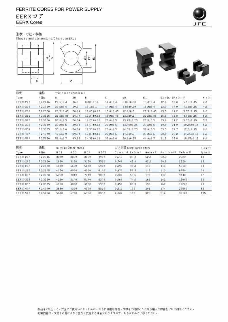
EERXコアEERX Cores
形状・寸法/特性Shapes and dimensions/Characteristics
形状 通称 寸法 Dimensions(mm)
Type Alias A 2B B C øD E1 E2 min. 2F min. F M min.
EERX-20A PQ2016 20.5±0.4 16.2 8.10±0.10 14.0±0.4 8.80±0.20 18.0±0.4 12.0 10.0 5.15±0.15 4.0
EERX-20B PQ2020 20.5±0.4 20.2 10.1±0.1 14.0±0.4 8.80±0.20 18.0±0.4 12.0 14.0 7.15±0.15 4.0
EERX-26A PQ2620 26.5±0.45 20.14 10.07±0.13 19.0±0.45 12.0±0.2 22.5±0.45 15.5 11.2 5.75±0.15 6.0
EERX-26B PQ2625 26.5±0.45 24.74 12.37±0.13 19.0±0.45 12.0±0.2 22.5±0.45 15.5 15.8 8.05±0.15 6.0
EERX-32A PQ3220 32.0±0.5 20.54 10.27±0.13 22.0±0.5 13.45±0.25 27.5±0.5 19.0 11.2 5.75±0.15 5.5
EERX-32B PQ3230 32.0±0.5 30.34 15.17±0.13 22.0±0.5 13.45±0.25 27.5±0.5 19.0 21.0 10.65±0.15 5.5
EERX-35A PQ3535 35.1±0.6 34.74 17.37±0.13 26.0±0.5 14.35±0.25 32.0±0.5 23.5 24.7 12.5±0.15 6.0
EERX-40A PQ4040 40.5±0.9 39.74 19.87±0.13 28.0±0.6 14.9±0.3 37.0±0.6 28.0 29.2 14.75±0.15 6.3
EERX-50A PQ5050 50.0±0.7 49.95 24.98±0.13 32.0±0.6 20.0±0.35 44.0±0.7 31.5 35.8 18.05±0.15 6.0
形状 通称 AL value(nH/N2)±25% コア定数 Core parameters Weight
Type Alias MB1 MB3 MB4 MBT1 C1(mm–1) Le(mm) Ae(mm2) Amin(mm2) Ve(mm3) (g/set)
EERX-20A PQ2016 3300 3880 3880 4900 0.610 37.4 62.0 60.8 2320 13
EERX-20B PQ2020 2690 3150 3150 3960 0.740 45.4 62.0 60.8 2820 15
EERX-26A PQ2620 4800 5630 5630 6920 0.390 46.3 119 113 5510 31
EERX-26B PQ2625 4150 4920 4920 6110 0.470 55.5 118 113 6550 36
EERX-32A PQ3220 6260 7310 7310 9360 0.330 55.5 170 142 9440 42
EERX-32B PQ3230 4290 5140 5140 6370 0.460 74.6 161 142 12000 55
EERX-35A PQ3535 4150 4860 4860 5980 0.450 87.9 196 162 17200 73
EERX-40A PQ4040 3680 4300 4300 5310 0.510 102 201 174 20500 95
EERX-50A PQ5050 5670 6720 6720 8330 0.344 113 328 314 37100 195
øD
E2
E1AM
B C
F

FERRITE CORES FOR POWER SUPPLY
EESコアEES Cores
形状・寸法/特性Shapes and dimensions/Characteristics
形状 寸法 Dimensions(mm)Fig.
Type A 2B B C D1 D2 E min. 2F min. F V W
EES-15A 15.0±0.3 15.0 7.50±0.20 4.65±0.20 5.30±0.20 2.40±0.15 10.6 10.6 5.50±0.20 0.20 2
EES-20A 20.0±0.4 20.0 10.0±0.25 6.70±0.30 8.90±0.25 3.50±0.20 15.1 14.9 7.70±0.25 0.15 1
EES-25A 24.7±0.65 25.0 12.5±0.25 9.70±0.20 11.4±0.2 5.20±0.15 18.1 18.1 9.30±0.25 0.50 1
EES-30A 30.0±0.8 30.0 15.0±0.25 9.20±0.20 14.6±0.25 4.80±0.25 21.65 21.8 11.2±0.3 0.75 1
形状 AL value(nH/N2)±25% コア定数 Core parameters Weight
Type MB1 MB3 MB4 MBT1 C1(mm–1) Le(mm) Ae(mm2) Amin(mm2) Ve(mm3) (g/set)
EES-15A 905 1070 1070 1330 2.14 33.6 15.7 12.7 527 3.0
EES-20A 1330 1590 1590 1990 1.50 47.6 31.7 29.5 1510 7.5
EES-25A 2140 2480 2480 3210 0.954 58.5 61.3 58.2 3590 18
EES-30A 2200 2640 2640 3350 0.951 69.7 73.3 69.9 5120 25
ED1
B
F
A
D2
V
C
D2
W
Fig.2
C
Fig.1
21Specifications which provide more details for the proper and safe use of the described product are available upon request.All specifications are subject to change without notice.

HIGH µ FERRITE CORES FOR EMI PREVENTION/EMC and PULSE TRANSFORMER
ETコアET Cores
形状・寸法/特性Shapes and dimensions/Characteristics
形状 寸法 Dimensions(mm)
Type A B C D H M
ET-20A 20.6±0.5 20.6±0.5 4.40±0.20 4.00±0.20 2.00±0.20 2.00±0.20ET-24A 24.2±0.5 24.2±0.5 4.00±0.30 4.00±0.20 2.40±0.15 2.40±0.15ET-28A 28.45±0.55 28.45±0.55 5.00±0.30 5.00±0.20 2.90±0.15 2.90±0.15ET-35A 35.3±0.6 35.3±0.6 7.50±0.30 7.50±0.25 4.00±0.25 4.00±0.20ET-35B 33.1±0.6 35.4±0.4 7.50±0.30 7.50±0.30 (3.80)* (3.80)*
*( ) are typical values.
形状 AL value(nH/N2) コア定数 Core parameters Weight
Type MA055 MA070 MA085 MA100 C1(mm–1) Le(mm) Ae(mm2) Amin(mm2) Ve(mm3) (g)
ET-20A 2340±30% 3050±30% 3610±30% 4250±30% 2.96 52.1 17.6 17.6 917 4.64
ET-24A 2020+40,–25% 2570+40,–25% 3130+45,–25% 3680+45,–25% 3.42 61.0 17.8 16.0 1090 5.62
ET-28A 2650+45,–25% 3370+45,–25% 4090+45,–25% 4820+45,–30% 2.61 71.4 27.4 25.0 1950 10.0
ET-35A 4670+40,–25% 5940+40,–25% 7220+40,–30% 8490+45,–30% 1.48 86.7 58.6 56.3 5080 25.9
ET-35B 4590+40,–25% 5840+40,–25% 7090+40,–30% 8340+45,–30% 1.51 85.5 56.7 56.3 4850 24.7
B
A
C
D
M M
HH
31Specifications which provide more details for the proper and safe use of the described product are available upon request.All specifications are subject to change without notice.

HIGH µ FERRITE CORES FOR EMI PREVENTION/EMC and PULSE TRANSFORMER
UTコアUT Cores
形状・寸法/特性Shapes and dimensions/Characteristics
形状 寸法 Dimensions(mm)
Type A B C D H M
UT-19.8A 19.8±0.3 13.2±0.4 3.60±0.20 3.60±0.20 3.60±0.20 3.00±0.20UT-20A 20.6±0.3 14.1±0.25 4.60±0.20 4.20±0.20 2.40±0.15 2.30±0.15UT-20S 20.6±0.3 14.1±0.25 4.60±0.20 4.20±0.20 2.40±0.15 2.30±0.15UT-129A 129.0±2.5 79.0±2.0 32.0±1.0 22.0±1.0 22.0±1.0 22.0±1.0
形状 AL value(nH/N2)+40,–30% コア定数 Core parameters Weight
Type MA055 MA070 MA085 MA100 C1(mm–1) Le(mm) Ae(mm2) Amin(mm2) Ve(mm3) (g)
UT-19.8A 1680 2140 2600 3050 4.11 49.7 12.1 10.8 600 3.15
UT-20A 1580 2200 2440 4.38 52.9 12.1 10.6 638 3.84
UT-20S 2870 4.38 52.9 12.1 10.6 638 3.84
UT-129A 15700 0.439 309 704 704 218000 1070
A
B
HD
C
M M
30 製品をより正しく、安全にご使用いただくために、さらに詳細な特性・仕様をご確認いただける納入仕様書をぜひご請求ください。記載内容は、改良その他により予告なく変更する場合がありますので、あらかじめご了承ください。

FERRITE CORES FOR EMI PREVENTION/EMC and PULSE TRANSFORMER
R(リング)コアR(Toroidal) Cores
エポキシ樹脂コーティング、コアの厚さ寸法(H)の異なる製品も製作いたします。当社営業所へお申しつけください。
Available for the epoxy insulation coating and differentcore thickness products. Please contact us.
形状 略称 寸法 Dimensions(mm)
Type Abbreviation øDo øDi H
R-3.5/1.9/1.2A R-3.5A 3.50±0.20 1.90±0.20 1.20±0.20R-3.5/1.9/1.5B R-3.5B 3.50±0.20 1.90±0.20 1.50±0.20R-3.8/1.9/2A R-3.8A 3.80±0.20 1.90±0.20 2.00±0.20R-6/3/1.5A R-6A 6.00±0.25 3.00±0.20 1.50±0.20R-6/3/2C R-6C 6.00±0.25 3.00±0.20 2.00±0.20R-6/3/3B R-6B 6.00±0.25 3.00±0.20 3.00±0.20R-6.3/3/3A R-6.3A 6.30±0.25 3.00±0.20 3.00±0.20R-8/4/2A R-8A 8.00±0.30 4.00±0.20 2.00±0.20R-8/4/4B R-8B 8.00±0.30 4.00±0.20 4.00±0.20R-9/5/3A R-9A 9.00±0.30 5.00±0.20 3.00±0.20R-9.9/4.7/2.5B R-9.9B 9.90±0.30 4.70±0.25 2.50±0.25R-9.9/4.7/4.7A R-9.9A 9.90±0.30 4.70±0.25 4.70±0.25R-10/6/4A R-10A 10.0±0.3 6.00±0.30 4.00±0.25R-10/6/5E R-10E 10.0±0.3 6.00±0.30 5.00±0.25R-10/6/6B R-10B 10.0±0.3 6.00±0.30 6.00±0.30R-12/6/4A R-12A 12.0±0.3 6.00±0.30 4.00±0.25R-12.7/7.6/6A R-12.7A 12.7±0.35 7.60±0.30 6.00±0.30R-12.7/7.9/6C R-12.7C 12.7±0.35 7.90±0.30 6.00±0.30R-12.7/7.9/6.35B R-12.7B 12.7±0.35 7.90±0.30 6.35±0.30R-13/7/5A R-13A 13.0±0.35 7.00±0.30 5.00±0.30R-13/7/5.5C R-13C 13.0±0.35 7.00±0.30 5.50±0.30R-13/7/6.5B R-13B 13.0±0.35 7.00±0.30 6.50±0.30R-13.8/7.3/3.6A R-13.8A 13.8±0.35 7.30±0.30 3.60±0.30R-14/7/3H R-14H 14.0±0.35 7.00±0.30 3.00±0.20R-14/7/5A R-14A 14.0±0.35 7.00±0.30 5.00±0.30R-14/7/7B R-14B 14.0±0.35 7.00±0.30 7.00±0.30R-14/8/4C R-14C 14.0±0.35 8.00±0.30 4.00±0.30R-14/8/7D R-14D 14.0±0.35 8.00±0.30 7.00±0.30R-14/9/5G R-14G 14.0±0.35 9.00±0.30 5.00±0.30R-16/10/5D R-16D 16.0±0.35 10.0±0.3 5.00±0.30R-16/10/7B R-16B 16.0±0.35 10.0±0.3 7.00±0.30R-16/12/8C R-16C 16.0±0.35 12.0±0.4 8.00±0.30R-16/7/4A R-16A 16.0±0.35 7.00±0.30 4.00±0.30R-16/7/8F R-16F 16.0±0.35 7.00±0.30 8.00±0.30R-17/11/6A R-17A 17.0±0.35 11.0±0.4 6.00±0.30R-18/10/7A R-18A 18.0±0.4 10.0±0.4 7.00±0.30R-18/12/6B R-18B 18.0±0.4 12.0±0.4 6.00±0.30R-18/12/8C R-18C 18.0±0.4 12.0±0.4 8.00±0.30R-18.5/9.8/5.2B R-18.5B 18.5±0.4 9.80±0.30 5.20±0.30R-18.5/9.8/7C R-18.5C 18.5±0.4 9.80±0.30 7.00±0.30R-18.5/9.8/10.3A R-18.5A 18.5±0.4 9.80±0.30 10.3±0.3R-18.5/9.8/13D R-18.5D 18.5±0.4 9.80±0.30 13.0±0.4R-19/13/6A R-19A 19.0±0.4 13.0±0.4 6.00±0.30R-20/10/5A R-20A 20.0±0.4 10.0±0.3 5.00±0.30R-20/12/4D R-20D 20.0±0.4 12.0±0.3 4.00±0.30R-20/12/8B R-20B 20.0±0.4 12.0±0.3 8.00±0.30R-20/12/10C R-20C 20.0±0.4 12.0±0.3 10.0±0.3R-21.5/14.5/8A R-21.5A 21.5±0.4 14.5±0.35 8.00±0.35R-22/14/6.5E R-22E 22.0±0.4 14.0±0.35 6.50±0.35R-22/14/8B R-22B 22.0±0.4 14.0±0.35 8.00±0.35R-22/14/10A R-22A 22.0±0.4 14.0±0.35 10.0±0.35R-22/14/13C R-22C 22.0±0.4 14.0±0.35 13.0±0.35R-22.1/13/6.4A R-22.1A 22.1±0.4 13.0±0.35 6.40±0.35R-24/14/9K R-24K 24.0±0.4 14.0±0.35 9.00±0.35
øDi H
øDo
形状・寸法/特性Shapes and dimensions/Characteristics
32 製品をより正しく、安全にご使用いただくために、さらに詳細な特性・仕様をご確認いただける納入仕様書をぜひご請求ください。記載内容は、改良その他により予告なく変更する場合がありますので、あらかじめご了承ください。

FERRITE CORES FOR EMI PREVENTION/EMC and PULSE TRANSFORMER
R(リング)コアR(Toroidal) Cores
形状 AL value(nH/N2)±30% コア定数 Core parameters Weight
Type MA055 MA070 MA085 MA100 MA120 MA150 C1(mm–1) Le(mm) Ae(mm2) Ve(mm3) (g)
R-3.5/1.9/1.2A 806 1030 1250 8.57 7.98 0.931 7.42 0.040
R-3.5/1.9/1.5B 1010 1280 1560 6.86 7.98 1.16 9.28 0.050
R-3.8/1.9/2A 1520 1940 2360 4.53 8.27 1.83 15.1 0.083
R-6/3/1.5A 1140 1460 1770 6.04 13.1 2.16 28.2 0.16
R-6/3/2C 1520 1940 2360 4.53 13.1 2.88 37.7 0.21
R-6/3/3B 2290 2910 3540 3.02 13.1 4.32 56.5 0.31
R-6.3/3/3A 2450 3120 3780 2.82 13.3 4.73 63.1 0.35
R-8/4/2A 1520 1940 2360 4.53 17.4 3.84 67.0 0.37
R-8/4/4B 3050 3880 4710 2.27 17.4 7.69 134 0.74
R-9/5/3A 1940 2470 3000 3530 3.56 20.8 5.83 121 0.65
R-9.9/4.7/2.5B 2050 2610 3170 3720 3.37 20.9 6.21 130 0.73
R-9.9/4.7/4.7A 3850 4900 5950 7000 1.79 20.9 11.7 244 1.4
R-10/6/4A 2250 2860 3470 4090 4900 6130 3.08 24.1 7.83 188 0.99
R-10/6/5E 2810 3580 4340 5110 6130 7660 2.46 24.1 9.79 236 1.2
R-10/6/6B 3370 4290 5210 6130 7360 9190 2.05 24.1 11.7 283 1.5
R-12/6/4A 3050 3880 4710 5550 6650 8320 2.27 26.1 11.5 301 1.7
R-12.7/7.6/6A 3390 4310 5240 6160 7390 9240 2.04 30.5 15.0 457 2.4
R-12.7/7.9/6C 3130 3990 4840 5700 6840 8550 2.21 31.2 14.1 441 2.3
R-12.7/7.9/6.35B 3320 4220 5120 6030 7240 9040 2.08 31.2 15.0 466 2.4
R-13/7/5A 3400 4330 5260 6190 7430 9290 2.03 29.5 14.5 429 2.3
R-13/7/5.5C 3750 4770 5790 6810 8170 10200 1.85 29.5 16.0 471 2.5
R-13/7/6.5B 4430 5630 6840 8050 9660 12100 1.56 29.5 18.9 557 3.0
R-13.8/7.3/3.6A 2520 3210 3900 4580 5500 6880 2.74 31.0 11.3 351 1.9
R-14/7/3H 2290 2910 3540 4160 4990 6240 3.02 30.5 10.1 308 1.7
R-14/7/5A 3810 4850 5890 6930 8320 10400 1.81 30.5 16.8 513 2.8
R-14/7/7B 5340 6790 8250 9700 11600 14600 1.29 30.5 23.5 718 4.0
R-14/8/4C 2460 3130 3810 4480 5370 6720 2.81 32.8 11.7 384 2.0
R-14/8/7D 4310 5480 6660 7830 9400 11800 1.60 32.8 20.5 671 3.6
R-14/9/5G 2430 3090 3760 4420 5300 6630 2.84 35.0 12.3 430 2.2
R-16/10/5D 2590 3290 4000 4700 5640 7050 2.67 39.4 14.7 580 3.0
R-16/10/7B 3620 4610 5590 6580 7900 9870 1.91 39.4 20.6 812 4.2
R-16/12/8C 2530 3220 3910 4600 5520 6900 2.73 43.4 15.9 689 3.4
R-16/7/4A 3640 4630 5620 6610 7940 9920 1.90 32.3 17.0 550 3.2
R-16/7/8F 7270 9260 11200 13200 15900 19800 0.95 32.3 34.0 1100 6.4
R-17/11/6A 2870 3660 4440 5220 6270 7840 2.41 42.6 17.7 755 3.9
R-18/10/7A 4530 5760 6990 8230 9870 12300 1.53 41.5 27.2 1130 6.0
R-18/12/6B 2680 3410 4140 4870 5840 7300 2.58 45.9 17.8 814 4.2
R-18/12/8C 3570 4540 5510 6490 7780 9730 1.94 45.9 23.7 1090 5.5
R-18.5/9.8/5.2B 3630 4630 5620 6610 7930 9910 1.90 41.6 21.9 910 4.9
R-18.5/9.8/7C 4890 6230 7560 8900 10700 13300 1.41 41.6 29.4 1220 6.6
R-18.5/9.8/10.3A 7200 9160 11100 13100 15700 19600 0.96 41.6 43.3 1800 9.8
R-18.5/9.8/13D 9090 11600 14000 16500 19800 24800 0.761 41.6 54.7 2270 12.3
R-19/13/6A 2500 3190 3870 4550 5460 6830 2.76 49.1 17.8 873 4.4
R-20/10/5A 3810 4850 5890 6930 8320 10400 1.81 43.6 24.0 1050 5.8
R-20/12/4D 2250 2860 3470 4090 4900 6130 3.08 48.1 15.7 754 3.9
R-20/12/8B 4500 5720 6950 8170 9810 12300 1.54 48.1 31.3 1510 7.9
R-20/12/10C 5620 7150 8680 10200 12300 15300 1.23 48.1 39.1 1880 9.9
R-21.5/14.5/8A 3470 4410 5360 6300 1.99 55.1 27.6 1520 7.8
R-22/14/6.5E 3230 4110 4990 5880 2.14 54.7 25.6 1400 7.2
R-22/14/8B 3980 5060 6150 7230 1.74 54.7 31.5 1720 8.9
R-22/14/10A 4970 6330 7680 9040 1.39 54.7 39.3 2150 11.1
R-22/14/13C 6460 8230 9990 11700 1.07 54.7 51.1 2790 14.4
R-22.1/13/6.4A 3740 4750 5770 6790 1.85 52.6 28.4 1500 7.9
R-24/14/9K 5340 6790 8250 9700 1.30 56.9 43.9 2500 13.2
33Specifications which provide more details for the proper and safe use of the described product are available upon request.All specifications are subject to change without notice.

FERRITE CORES FOR EMI PREVENTION/EMC and PULSE TRANSFORMER
R(リング)コアR(Toroidal) Cores
エポキシ樹脂コーティング、コアの厚さ寸法(H)の異なる製品も製作いたします。当社営業所へお申しつけください。
Available for the epoxy insulation coating and differentcore thickness products. Please contact us.
形状 略称 寸法 Dimensions(mm)
Type Abbreviation øDo øDi H
R-25/15/4G R-25G 25.0±0.5 15.0±0.4 4.00±0.40R-25/15/6J R-25J 25.0±0.5 15.0±0.4 6.00±0.40R-25/15/7.7D R-25D 25.0±0.5 15.0±0.4 7.70±0.40R-25/15/8C R-25C 25.0±0.5 15.0±0.4 8.00±0.40R-25/15/10E R-25E 25.0±0.5 15.0±0.4 10.0±0.4R-25/15/12A R-25A 25.0±0.5 15.0±0.4 12.0±0.4R-25/15/13B R-25B 25.0±0.5 15.0±0.4 13.0±0.4R-25/15/15H R-25H 25.0±0.5 15.0±0.4 15.0±0.4R-28/19.1/10C R-28C 28.0±0.5 19.1±0.5 10.0±0.4R-28/19.1/11D R-28D 28.0±0.5 19.1±0.5 11.0±0.4R-28/19.1/12A R-28A 28.0±0.5 19.1±0.5 12.0±0.4R-30.5/19/13A R-30.5A 30.5±0.5 19.0±0.5 12.9±0.3R-31/14/5K R-31K 31.0±0.5 14.0±0.5 5.00±0.40R-31/19/5J R-31J 31.0±0.5 19.0±0.5 5.00±0.40R-31/19/6L R-31L 31.0±0.5 19.0±0.5 6.00±0.40R-31/19/7H R-31H 31.0±0.5 19.0±0.5 7.00±0.40R-31/19/8A R-31A 31.0±0.5 19.0±0.5 8.00±0.40R-31/19/13C R-31C 31.0±0.5 19.0±0.5 13.0±0.4R-31/19/15D R-31D 31.0±0.5 19.0±0.5 15.0±0.4R-31/20/10B R-31B 31.0±0.5 20.0±0.5 10.0±0.4R-31/20/15E R-31E 31.0±0.5 20.0±0.5 15.0±0.4R-36/23/7B R-36B 36.0±0.6 23.0±0.5 7.00±0.40R-36/23/15A R-36A 36.0±0.6 23.0±0.5 15.0±0.4R-37/22/6C R-37C 37.0±0.6 22.0±0.5 6.00±0.50R-37/22/13B R-37B 37.0±0.6 22.0±0.5 13.0±0.4R-37/22/15A R-37A 37.0±0.6 22.0±0.5 15.0±0.4R-38/19/13A R-38A 38.0±0.7 19.0±0.5 13.0±0.5R-38.1/19/12.7A R-38.1A 38.1±0.7 19.0±0.5 12.7±0.4R-39/20/6A R-39A 39.0±0.7 20.0±0.5 6.00±0.50R-39/20/7B R-39B 39.0±0.7 20.0±0.5 7.00±0.50R-44.5/30/13A R-44.5A 44.5±0.7 30.0±0.5 13.0±0.4R-47/27/15A R-47A 47.0±0.8 27.0±0.5 15.0±0.5R-48/30/15A R-48A 48.0±0.8 30.0±0.5 15.0±0.5R-50/25/10A R-50A 50.0±0.8 25.0±0.5 10.0±0.5R-50/25/15B R-50B 50.0±0.8 25.0±0.5 15.0±0.5R-50/25/19D R-50D 50.0±0.8 25.0±0.5 19.0±0.5R-51/31/13A R-51A 51.0±0.7 31.0±0.5 13.0±0.4R-56/36/20A R-56A 56.0±0.8 36.0±0.5 20.0±0.5R-60/36/20C R-60C 60.0±0.8 36.0±0.5 20.0±0.5R-60/40/18A R-60A 60.0±0.8 40.0±0.5 18.0±0.5R-60/40/25B R-60B 60.0±0.8 40.0±0.5 25.0±0.5R-63/38/25A R-63A 63.0±0.9 38.0±0.7 25.0±0.8R-68/44/13.5B R-68B 68.0±1.0 44.0±0.8 13.5±0.5R-68/44/15A R-68A 68.0±1.0 44.0±0.8 15.0±0.5R-78/51/16A R-78A 78.0±1.5 50.5±1.5 16.0±1.5R-78/51/22B R-78B 78.0±1.5 50.5±1.5 22.0±1.5R-78/51/25C R-78C 78.0±1.5 50.5±1.5 25.0±1.5R-82/55/20A R-82A 82.0±1.6 55.0±1.0 20.0±0.5R-96/75/24A R-96A 96.0±2.5 75.0±2.5 24.0±1.0R-98.5/63/20A R-98.5A 98.5±2.0 63.0±2.0 20.0±1.0R-102/61/21A R-102A 102.0±2.5 61.0±1.5 21.0±0.5R-102/61/23B R-102B 102.0±2.5 61.0±1.5 23.0±0.5R-117/80/23A R-117A 117.0±2.5 80.0±2.0 23.0±1.0R-128/105/33C R-128C 128.0±2.5 104.5±2.5 33.5±1.0
øDi H
øDo
形状・寸法/特性Shapes and dimensions/Characteristics
34 製品をより正しく、安全にご使用いただくために、さらに詳細な特性・仕様をご確認いただける納入仕様書をぜひご請求ください。記載内容は、改良その他により予告なく変更する場合がありますので、あらかじめご了承ください。

FERRITE CORES FOR EMI PREVENTION/EMC and PULSE TRANSFORMER
R(リング)コアR(Toroidal) Cores
形状 AL value(nH/N2)±30% コア定数 Core parameters Weight
Type MA055 MA070 MA085 MA100 MA120 MA150 C1(mm–1) Le(mm) Ae(mm2) Ve(mm3) (g)
R-25/15/4G 2250 2860 3470 4090 3.08 60.2 19.6 1180 6.2
R-25/15/6J 3370 4290 5210 6130 2.05 60.2 29.4 1770 9.2
R-25/15/7.7D 4330 5510 6690 7870 1.60 60.2 37.7 2270 11.9
R-25/15/8C 4500 5720 6950 8170 1.54 60.2 39.1 2360 12.3
R-25/15/10E 5620 7150 8680 10200 1.23 60.2 48.9 2940 15.4
R-25/15/12A 6740 8580 10400 12300 1.03 60.2 58.7 3530 18.5
R-25/15/13B 7300 9300 11300 13300 0.946 60.2 63.6 3830 20.0
R-25/15/15H 8430 10700 13000 15300 0.82 60.2 73.4 4420 23.1
R-28/19.1/10C 4210 5360 6500 7650 1.64 72.2 44.0 3170 16.1
R-28/19.1/11D 4630 5890 7150 8420 1.49 72.2 48.4 3490 17.7
R-28/19.1/12A 5050 6430 7800 9180 1.37 72.2 52.8 3810 19.4
R-30.5/19/13A 6720 8550 10400 1.03 74.9 72.8 5460 28.3
R-31/14/5K 4370 5560 6760 7950 1.58 63.8 40.3 2570 14.7
R-31/19/5J 2690 3430 4160 4900 2.57 75.5 29.4 2220 11.5
R-31/19/6L 3230 4110 4990 5870 2.14 75.5 35.3 2660 13.9
R-31/19/7H 3770 4800 5830 6850 1.83 75.5 41.2 3110 16.2
R-31/19/8A 4310 5480 6660 7830 1.60 75.5 47.1 3550 18.5
R-31/19/13C 7000 8910 10800 0.987 75.5 76.5 5770 30.0
R-31/19/15D 8080 10300 12500 0.856 75.5 88.2 6660 34.6
R-31/20/10B 4820 6140 7450 1.43 77.6 54.1 4200 21.6
R-31/20/15E 7230 9200 11200 0.956 77.6 81.2 6300 32.4
R-36/23/7B 3450 4390 5330 2.00 89.6 44.7 4010 20.7
R-36/23/15A 7390 9410 11400 0.935 89.6 95.9 8600 44.3
R-37/22/6C 3430 4370 5300 2.01 88.6 44.0 3900 20.4
R-37/22/13B 7430 9460 11500 0.930 88.6 95.3 8450 44.3
R-37/22/15A 8580 10900 13300 0.806 88.6 110 9750 51.1
R-38/19/13A 9910 12600 15300 0.697 82.7 119 9820 54.2
R-38.1/19/12.7A 9720 12400 15000 0.711 82.8 117 9650 53.3
R-39/20/6A 4410 5610 6810 1.57 86.1 54.9 4730 25.9
R-39/20/7B 5140 6540 7950 1.34 86.1 64.1 5520 30.2
R-44.5/30/13A 5640 7180 8710 1.23 114 93.0 10600 54.0
R-47/27/15A 9150 11600 14100 0.756 110 146 16200 85.4
R-48/30/15A 7760 9870 0.891 118 133 15700 81.0
R-50/25/10A 7620 9700 0.906 109 120 13100 72.2
R-50/25/15B 11400 14600 0.604 109 180 19600 108
R-50/25/19D 14500 18400 0.477 109 228 24800 137
R-51/31/13A 7120 9060 0.971 124 127 15700 82.0
R-56/36/20A 9720 12400 0.711 140 197 27500 142
R-60/36/20C 11200 14300 0.615 144 235 33900 177
R-60/40/18A 8030 10200 0.861 153 178 27100 139
R-60/40/25B 11200 14200 0.620 153 247 37700 192
R-63/38/25A 13900 17700 0.497 152 306 46500 243
R-68/44/13.5B 6460 8230 1.07 170 159 27200 140
R-68/44/15A 7180 9140 0.962 170 177 30200 155
R-78/51/16A 7200 0.903 196 217 42400 218
R-78/51/22B 9890 0.657 196 298 58300 299
R-78/51/25C 11200 0.578 196 338 66200 340
R-82/55/20A 7670 0.787 210 266 55800 285
R-96/75/24A 6190 1.06 266 251 66700 332
R-98.5/63/20A 8800 0.703 245 349 85700 441
R-102/61/21A 9720 0.582 245 421 103000 540
R-102/61/23B 11700 0.531 245 461 113000 592
R-117/80/23A 8720 0.719 302 420 127000 645
R-128/105/33C 6760 0.925 363 392 142000 704
35Specifications which provide more details for the proper and safe use of the described product are available upon request.All specifications are subject to change without notice.